Unlock instant, AI-driven research and patent intelligence for your innovation.
3D additive-manufacturing bilateral laser welding method for T-shaped structure
What is Al technical title?
Al technical title is built by PatSnap Al team. It summarizes the technical point description of the patent document.
A technology of laser welding and welding methods, applied in laser welding equipment, welding equipment, metal processing equipment, etc., can solve problems such as difficult to ensure welding wire, difficult welding seam structure alloy control, etc., to achieve high density, uniform alloy control, forming uniform effect
Active Publication Date: 2016-06-29
HARBIN INST OF TECH
View PDF7 Cites 10 Cited by
Summary
Abstract
Description
Claims
Application Information
AI Technical Summary
This helps you quickly interpret patents by identifying the three key elements:
Problems solved by technology
Method used
Benefits of technology
Problems solved by technology
[0004] In order to solve the problem of high welding speed and long welding bead, the double-sided laser welding process of T-shaped structure is difficult to ensure that the welding wire is continuously and stably fed into the molten pool at a constant speed, and one-time welding can obtain uniform, continuous and defect-free double-sided welding. It is difficult to flexibly control the specific alloy of the weld seam, and a 3D additive T-shaped structure double-sided laser welding method is proposed.
Method used
Image
Click on the blue label to locate the original text in one second.
Reading with bidirectional positioning of images and text.
Examples
specific Embodiment approach 1
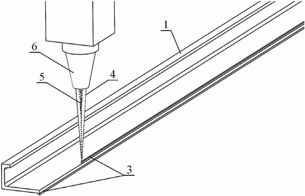
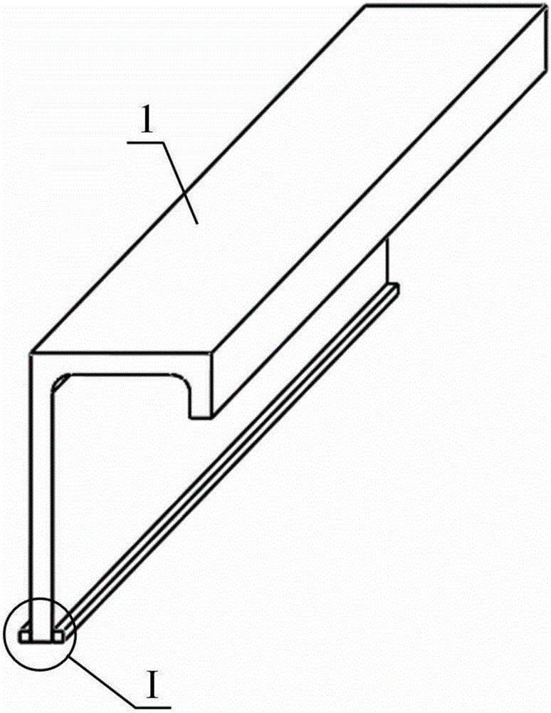
[0019] Specific implementation mode one: combine Figure 1 to Figure 4 Illustrate this embodiment, the welding method of this embodiment is to the welding of T-shaped structure of aircraft wall plate, this T-shaped structure is welded by vertical long stringer 1 and horizontally placed skin 2, and concrete welding method is through This is achieved by the following steps:
[0020] Step 1, chemically cleaning the surface of the stringer 1 to remove the oxide film and oil stains;
[0021] Step 2, designing the deposition layer 3: designing the deposition layer 3 on the area to be welded on the surface of the girder 1, the cross section of the deposition layer 3 is square or rectangular;
[0022] Step 3: Place the laser cladding head 6 vertically directly above the area to be welded on the surface of the stringer 1, and use the coaxial feeding method of the laser beam 4 and the alloy powder 5 to perform laser 3D on the area to be welded on both sides of the stringer 1 Add mater...
specific Embodiment approach 2
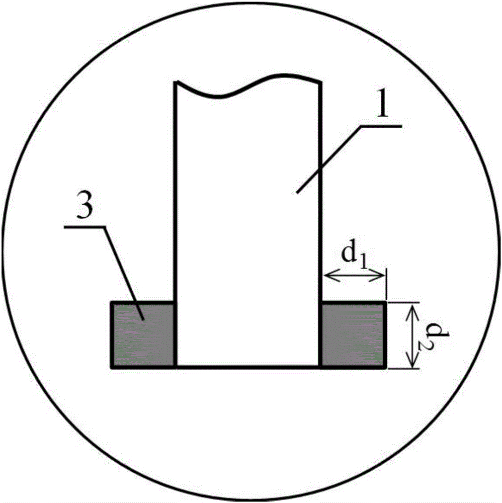
[0024] Specific implementation mode two: combination image 3 Describe this embodiment mode, this embodiment mode is that the cross-section of deposition layer 3 in step 2 is a square, namely d 1 = d 2 , d 1 and d 2 The following relation is satisfied: d 1 d 2 = π·r 2 · v / V, where d 1 is the deposition layer width, d 2 is the height of the deposited layer, r is the radius of the welding wire used in conventional double-sided laser wire-filling welding, v is the wire feeding speed, and V is the welding speed. Other steps are the same as in the first embodiment.
specific Embodiment approach 3
[0025] Specific implementation mode three: combination image 3 Describe this embodiment mode, this embodiment mode is that the cross-section of deposition layer 3 in step 2 is rectangular, namely d 1 ≠ d 2 , d 1 and d 2 The following relation is satisfied: d 1 d 2 = π·r 2 ·v / V, where r is the radius of the welding wire used in conventional double-sided laser wire-filling welding, v is the wire feeding speed, and V is the welding speed. Other steps are the same as in the first embodiment.
PUM
Property
Measurement
Unit
thickness
aaaaa
aaaaa
Abstract
The invention provides a 3D additive-manufacturing bilateral laser welding method for a T-shaped structure, relates to a double-laser-beam welding method, and aims to solve the problems that under the conditions of high welding speed and long weld beads, in a bilateral laser welding process of a T-shaped structure, the circumstance that welding wires are continuously and stably fed into a molten pool at constant speed and even, coherent and non-defective bilateral weld joints are obtained by one-time welding is difficult to ensure, and alloy of weld microstructures is difficult to regulate and control specifically and flexibly. The method comprises the following steps: 1, chemically cleaning the surface of a stringer; 2, designing of a sedimentary layer: designing the sedimentary layer in a region to be welded on the surface of the stringer, wherein the cross section of the sedimentary layer is square or rectangular; 3, vertically placing a laser cladding head at a position right above the region to be welded on the surface of the stringer, carrying out laser 3D additive-manufacturing on regions to be welded on two sides of the stringer to obtain the sedimentary layer in a mode of coaxially feeding laser beams and alloy powder; and 4, carrying out bilateral laser welding on the stringer and an envelope to obtain bilateral symmetric weld joints. The 3D additive-manufacturing bilateral laser welding method for the T-shaped structure is used for double-laser welding of the T-shaped structure.
Description
technical field [0001] The invention relates to a double-laser beam welding method, in particular to a 3D additive T-shaped structure double-sided laser welding method, which can be applied to the welding process of long stringers and skins in the manufacturing process of aircraft wall panels. Background technique [0002] Aircraft fuselage panels are mainly composed of long stringer-skin T-shaped structures, which previously had to be connected by traditional riveting methods. However, riveting is not only inefficient in production, but also adds extra weight to the airframe, reducing the fuel economy of the aircraft. In the early 1990s, Airbus carried out the research on the double-sided laser welding technology of the T-shaped structure of the fuselage panel, and successfully used this technology to replace the welding of riveting to the T-shaped structure of the long truss-skin. Compared with traditional riveting technology, this double-sided laser welding technology ha...
Claims
Application Information
Patent Timeline
Application Date:The date an application was filed.
Publication Date:The date a patent or application was officially published.
First Publication Date:The earliest publication date of a patent with the same application number.
Issue Date:Publication date of the patent grant document.
PCT Entry Date:The Entry date of PCT National Phase.
Estimated Expiry Date:The statutory expiry date of a patent right according to the Patent Law, and it is the longest term of protection that the patent right can achieve without the termination of the patent right due to other reasons(Term extension factor has been taken into account ).
Invalid Date:Actual expiry date is based on effective date or publication date of legal transaction data of invalid patent.

