Mechanical gripper

A mechanical gripper and finger technology, applied in the field of automation, can solve the problems of limited adjustment range of clamping space, poor versatility and controllability, cumbersome adjustment process, etc., so as to shorten the installation and debugging time, reduce the scrap rate, and improve the general sexual effect

Inactive Publication Date: 2016-06-29
SHENZHEN BONMET ROBOT CO LTD
View PDF9 Cites 20 Cited by
  • Summary
  • Abstract
  • Description
  • Claims
  • Application Information

AI Technical Summary

Problems solved by technology

At the same time, the adjustment range of the clamping space of the existing mechanical gripper is limited, and manual adjustment is required, and the adjustment process is cumbersome
Therefore, in processing engineering, when the shape and size of the workpiece cha

Method used


Image

  • Mechanical gripper
  • Mechanical gripper
  • Mechanical gripper

Examples


Example Embodiment

[0035] It should be understood that the specific embodiments described here are only used to explain the present invention, not to limit the present invention.

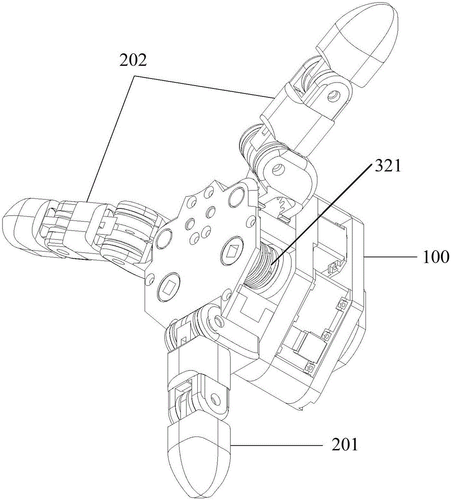
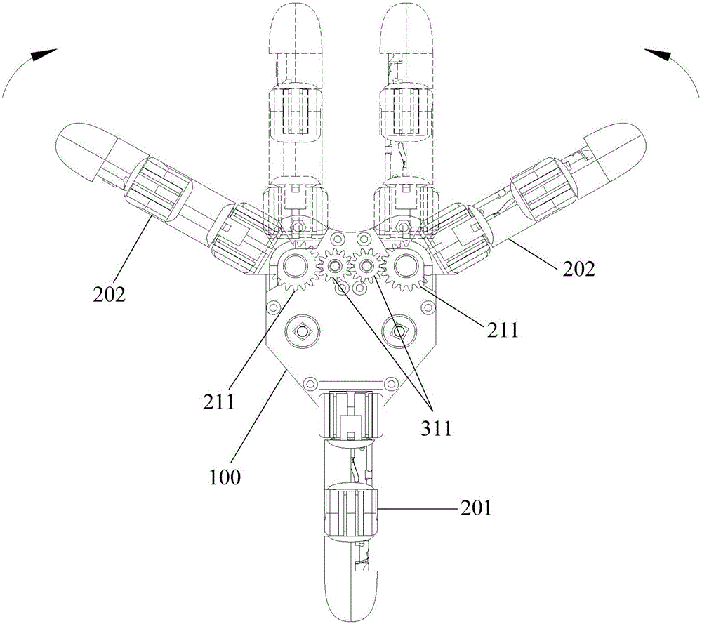
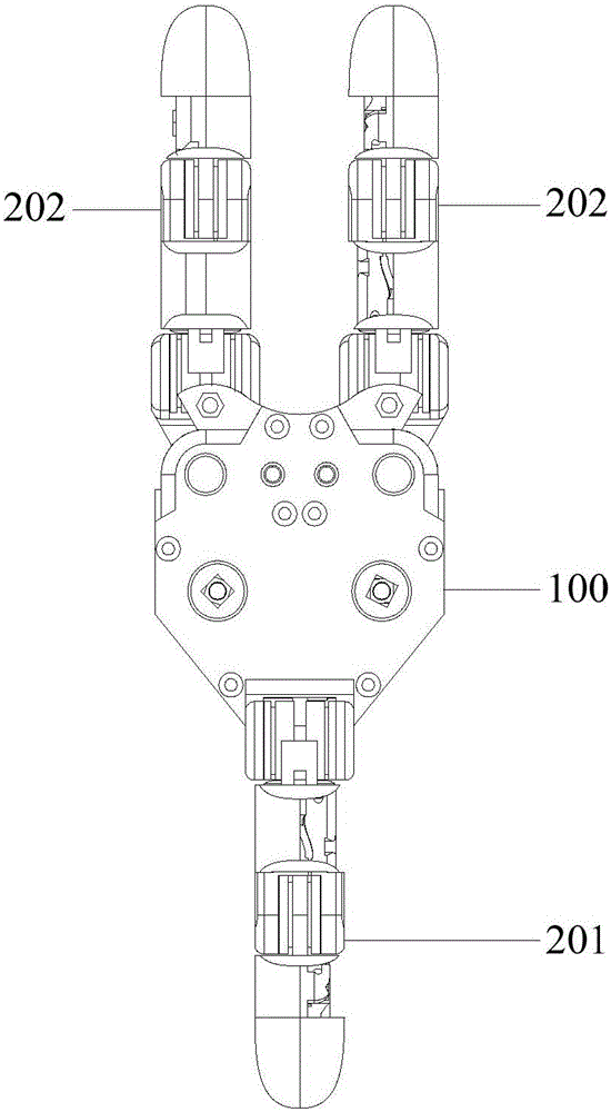
[0036] see Figure 1-Figure 7 , an embodiment of the mechanical gripper of the present invention is proposed, the mechanical gripper includes a base 100, a first drive mechanism installed on the base 100 and three finger assemblies (201, 202) connected to the base 100, the three fingers A clamping space is formed between the components (201, 202), which can clamp workpieces. One finger assembly 201 is fixedly connected to the base 100 , and the other two finger assemblies 202 are movably connected to the base 100 . There is a certain included angle between the three finger assemblies (201, 202), and the first drive mechanism drives the two finger assemblies 202 movably connected to the base 100 to rotate to change the size of the included angle between the three finger assemblies (201, 202). like figure 2 Shown is...


PUM


Abstract

The invention discloses a mechanical gripper. The mechanical gripper comprises a base, a first driving mechanism and three finger assemblies, wherein the first driving mechanism is mounted on the base, and the three finger assemblies are connected to the base; a certain inclined angle is formed between every two adjacent finger assemblies; two finger assemblies are movably connected to the base, and the first driving mechanism is used for driving the two finger assemblies movably connected to the base to rotate so as to change the size of the inclined angles; therefore, the same mechanism gripper can clamp workpieces of various shapes, the application scope of the mechanical gripper is enlarged, and the generality of the mechanical gripper is improved. The mechanical gripper disclosed by the embodiment of the invention is used for clamping and processing different workpieces, the mechanical gripper does not need to be exchanged frequently, and the clamping space does not need to be debugged, so that the mounting and debugging time is greatly shortened, the scrap factor of the workpieces is also greatly reduced, and the production efficiency is greatly improved.

Description

technical field [0001] The invention relates to the technical field of automation, in particular to a mechanical gripper. Background technique [0002] In the automatic processing process, it is necessary to use the mechanical gripper to automatically clamp the workpiece. Existing mechanical grippers usually use cylinder drive + lever mechanism to realize the automatic clamping of workpieces. The cylinders include two-finger parallel cylinders, three-finger circular cylinders, and four-finger circular cylinders, etc., and some use electric clamping fixtures To realize the clamping of the workpiece, these clamping methods cannot adjust the clamping force, which is easy to damage the fragile workpiece. [0003] The fingers of known mechanical grippers usually have two types, one is two relatively fixed fingers, which can only be used to clamp regular-shaped workpieces such as rectangles; the other is three evenly distributed and fixed fingers , mainly used to clamp round and...

Claims


Application Information

Patent Timeline
IPC IPC(8): B25J9/12B25J15/10
CPCB25J9/12B25J15/103
Inventor 吴琼海董加归
Owner SHENZHEN BONMET ROBOT CO LTD
Why Eureka
Try Eureka