Valve pin decoupling of hot runner synchronization plate

A technology of synchronous plate and valve pin, applied in the field of valve pin decoupling device, can solve the problems of large axial installation space, difficult service, unreliable decoupling valve pin, etc., and achieve the effect of small axial structure size and simple effort

Active Publication Date: 2018-05-15
奥托门纳创新有限责任公司
View PDF4 Cites 0 Cited by
  • Summary
  • Abstract
  • Description
  • Claims
  • Application Information

AI Technical Summary

Problems solved by technology

For example, some of these devices present a complex structure and / or require a large axial installation space in the hot runner synchronizing plate, while others are based on the rated breaking point of the safety element, which makes it possible after the valve pin is decoupled, Returning to service on these units is more difficult, or unreliable to decouple valve pins at predetermined overload values

Method used


Image

  • Valve pin decoupling of hot runner synchronization plate
  • Valve pin decoupling of hot runner synchronization plate
  • Valve pin decoupling of hot runner synchronization plate

Examples


Embodiment Construction

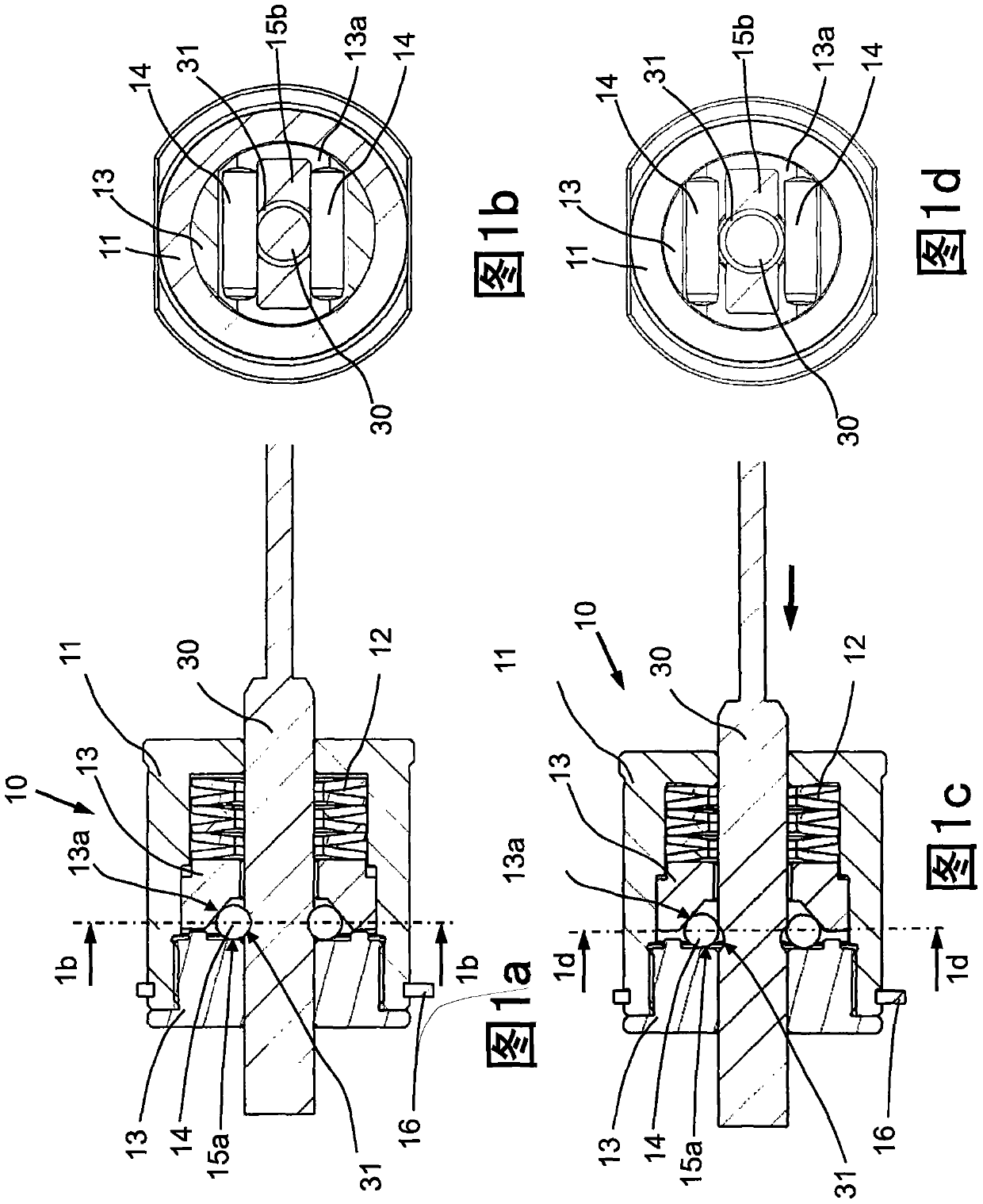
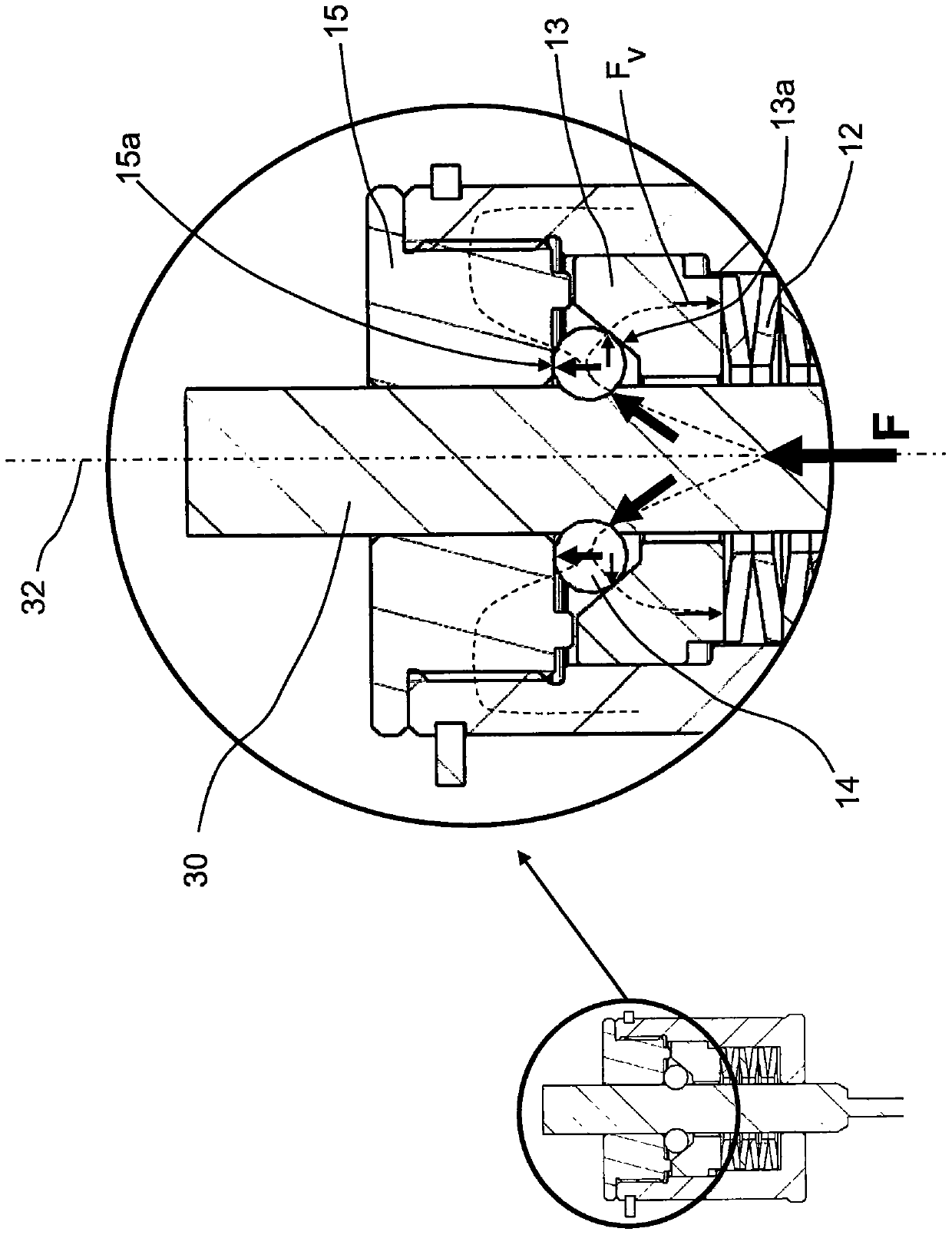
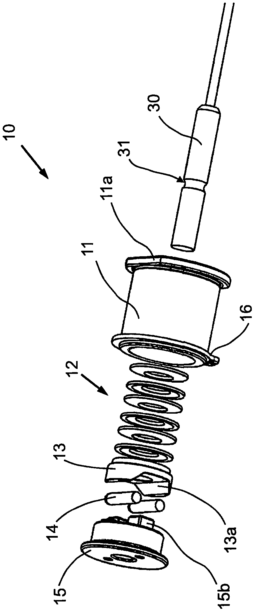
[0043] Figure 1a It is a cross-sectional view showing the valve pin decoupling device 10 in the coupled state of the exemplary embodiment of the present invention. The valve pin decoupling device 10 comprises a sleeve 11 which supports a valve pin 30 . Arranged in the sleeve 11 is biasing means 12 which in the exemplary embodiment is realized by a coil spring assembly. Furthermore, a thrust element 13 is arranged in the sleeve 11 and a biasing means 12 applies a force to the thrust element. The exemplary valve pin 30 includes a peripheral retaining groove 31 in which the two retaining elements 14 are received.

[0044] A cover 15 is arranged on the end of the sleeve 11, said cover being opposite to the biasing means 12; the cover 15 is fixedly screwed onto the sleeve. In the installed state of the valve pin decoupling device 10, the cover 15 is thus arranged on the side of the synchronizing plate facing away from the mold cavity (on Figure 6a shown in ). The cover 15 of ...


PUM


Abstract

A valve pin decoupling device for a synchronous plate of an injection molding machine accommodates a valve pin that can be moved along a valve pin axis by the synchronous plate for controlling the supply of melt into a mold cavity. The valve pin includes at least one retaining groove where the valve pin can be connected to the synchronization plate. The valve pin decoupling device comprises at least one retaining element with which a connection between the valve pin and the synchronization plate can be established. Furthermore, the valve pin decoupling device includes a cover, which is fixedly arranged on the synchronization plate. At least one first holding surface is formed on the cover, and the at least one holding element is arranged on the first holding surface. The valve pin decoupling device further comprises biasing means and a thrust element having at least one second retaining surface inclined with respect to the valve pin axis, and the at least one retaining element is arranged at the second retaining surface .

Description

technical field [0001] The invention relates to a valve pin decoupling device for a hot runner synchronous plate of an injection molding machine, the injection molding machine including a hot runner system, the valve pin decoupling device is used to decouple the valve when an overload occurs on the valve pin pin. Background technique [0002] Valve pin decoupling devices are known. They are used, for example, to protect the valve pin and the components of the hot runner system in communication with the valve pin against damage occurring against a controlled movement of the valve pin in the event of a failure of the heating device in the corresponding area. Known valve pin decoupling devices entail various disadvantages. For example, some of these devices present a complex structure and / or require a large axial installation space in the hot runner synchronizing plate, while others are based on the rated breaking point of the safety element, which makes it possible after the...

Claims


Application Information

Patent Timeline
Patent Type & Authority Patents(China)
IPC IPC(8): B29C45/28
CPCB29C45/84B29C45/2806
Inventor P·克恩
Owner 奥托门纳创新有限责任公司
Why Eureka
Try Eureka