Base of a punching machine and its installation method

An installation method and punching machine technology, applied in the direction of presses, manufacturing tools, etc., can solve the problems of upper die offset, workpiece quality impact, etc., achieve the effect of small rebound, good integrity, and avoid small offset

Inactive Publication Date: 2017-09-19
刘媛
View PDF1 Cites 0 Cited by
  • Summary
  • Abstract
  • Description
  • Claims
  • Application Information

AI Technical Summary

Problems solved by technology

[0003] However, people have found in actual use that due to the impact of assembly accuracy, the vibration and aftershocks generated by the large-tonnage punch press during stamping will cause the upper die to shift slightly, and in severe cases, the upper die and the upper die seat will be 1 to the lower die. -5° included angle, which has a great impact on the quality of the workpiece in subsequent processing

Method used


Image

  • Base of a punching machine and its installation method
  • Base of a punching machine and its installation method
  • Base of a punching machine and its installation method

Examples


Embodiment 1

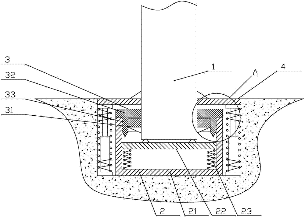
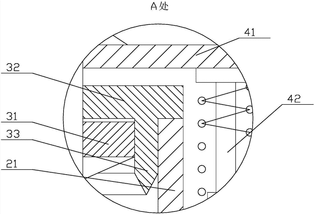
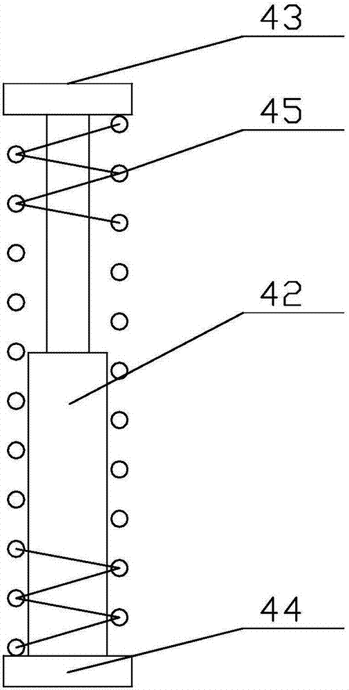
[0042]Embodiment 1: The damping rod 42 includes an inner rod body 421, an outer rod body 422 and a sealing plate 423, the inner rod body 421 is hollow with an open bottom, and the outer rod 422 is hollow with an open top. The inner rod body 421 is slidably connected to the top opening of the outer rod body 422, the sealing plate 423 is fixedly connected to the bottom opening of the inner rod body 421, and at least one flow hole is opened on the sealing plate 423, and the outer rod body 422 Filled with hydraulic oil. In this way, when the inner rod body and the outer rod body move relative to each other, the hydraulic oil flowing through the flow hole 1 will provide sufficient damping effect, so as to effectively slow down and resist rebound.

Embodiment 2

[0043] Embodiment 2: The damping rod 42 includes a fixed rod pile 424, a movable rod body 425 and a piston plate 426. The fixed rod pile 424 is hollow and has a sliding hole on the top, and the movable rod body 425 is penetrated in the In the sliding hole, the piston plate 426 is slidably connected in the fixed rod pile 424, the piston plate 426 is fixedly connected to the bottom end of the movable rod body 425, and at least one flow hole 2 is opened on the piston plate 426, and the fixed The pole pile 424 is filled with hydraulic oil. In this way, when the movable rod body performs telescopic movement relative to the fixed rod pile, the hydraulic oil flowing through the flow hole 1 will provide sufficient damping effect, so as to effectively slow down and resist rebound.

[0044] Follow these steps:

[0045] 1) Preset installation position: dig a deep pit on the ground to accommodate the base, and level and compact the bottom of the pit;

[0046] 2) Install the buffer assem...


PUM


Abstract

The invention discloses a base of a punching machine and an installation method of the base, and relates to the field of punching machine structures, in particular to an improvement on the base of the punching machine. According to the base of the punching machine and the installation method of the base, the structure is exquisite, installation is convenient, the stability is high, influences on the work environment are small, and vibration and follow-up aftershock generated during stamping can be effectively offset and filtered after the base and the installation method are used. A bearing barrel is in a straight barrel shape, a plurality of vertical sliding rails are evenly distributed on the inner wall of the bearing barrel, a plurality of sliding blocks matched with the sliding rails are fixedly connected to the side surface of a bearing plate, the bearing plate is horizontally arranged, and the multiple sliding blocks are connected into the sliding rails in a sliding manner; and bearing springs are vertically arranged and evenly distributed between the bottom face of the bearing plate and the barrel bottom of the bearing barrel, and the punching machine is erected on the top face of the bearing plate. The whole base has the beneficial effects of being good in integrality, high in anti-excursion capacity, good in vibration eliminating effect, high in vibration eliminating efficiency, small in springback amplitude and free of aftershock; and the machining accuracy and the running stability of the punching machine are guaranteed to the maximum degree.

Description

technical field [0001] The invention relates to the field of punch press structure, in particular to the improvement of the punch base. Background technique [0002] Punch presses are currently widely used in various fields, and the larger the size of the punch press, the greater the vibration, which not only has a great impact on the working environment, but also greatly reduces the service life of the punch press. In this regard, on December 17, 2014, the National Bureau of the State Council published a Chinese invention patent application entitled "A Device for Shock Absorption of Punch Presses" with the application number "201410412866.3". The technical solution formed by several spring-supported supports can effectively absorb shock after being installed on the bottom of the punch press. [0003] However, people have found in actual use that due to the impact of assembly accuracy, the vibration and aftershocks generated by the large-tonnage punch press during stamping ...

Claims


Application Information

Patent Timeline
Patent Type & Authority Patents(China)
IPC IPC(8): B30B15/00B30B15/04
CPCB30B15/0076B30B15/04
Inventor 刘媛
Owner 刘媛
Why Eureka
Try Eureka