
A full hydraulic drilling rig suspension weight control valve group

A control valve and full hydraulic technology, which is applied to rotary drilling rigs, mechanical equipment, earthwork drilling, etc., can solve the problems of failure to realize the suspension weight control of deep drilling, pipeline collision damage, poor working environment, etc., and achieve easy automation Effects of control, avoidance of safety accidents, and avoidance of stalls

Active Publication Date: 2018-08-03
RG PETRO MACHINERY GROUP
View PDF6 Cites 0 Cited by
  • Summary
  • Abstract
  • Description
  • Claims
  • Application Information

AI Technical Summary

Problems solved by technology

If the weight of the drill string is too large, the pressure exerted on the formation is too large, and the drill bit cannot drill. In this case, it is necessary to realize the suspended weight. At present, the hydraulic cylinder lifting system in the industry only installs a one-way balance valve at the oil port of the hydraulic cylinder. The stability and braking function of the lowering process has been realized, but the suspended weight control during deep drilling has not been realized; the pipelines in the hydraulic system are exposed to the outside for a long time and are prone to aging, and at the same time, the pipelines are easily damaged by collisions, and the connection points are prone to leakage; at the same time, in actual work , the working environment is relatively poor, it is easy to cause damage to the suspension control

Method used


Image

  • A full hydraulic drilling rig suspension weight control valve group
  • A full hydraulic drilling rig suspension weight control valve group
  • A full hydraulic drilling rig suspension weight control valve group

Examples


Embodiment Construction

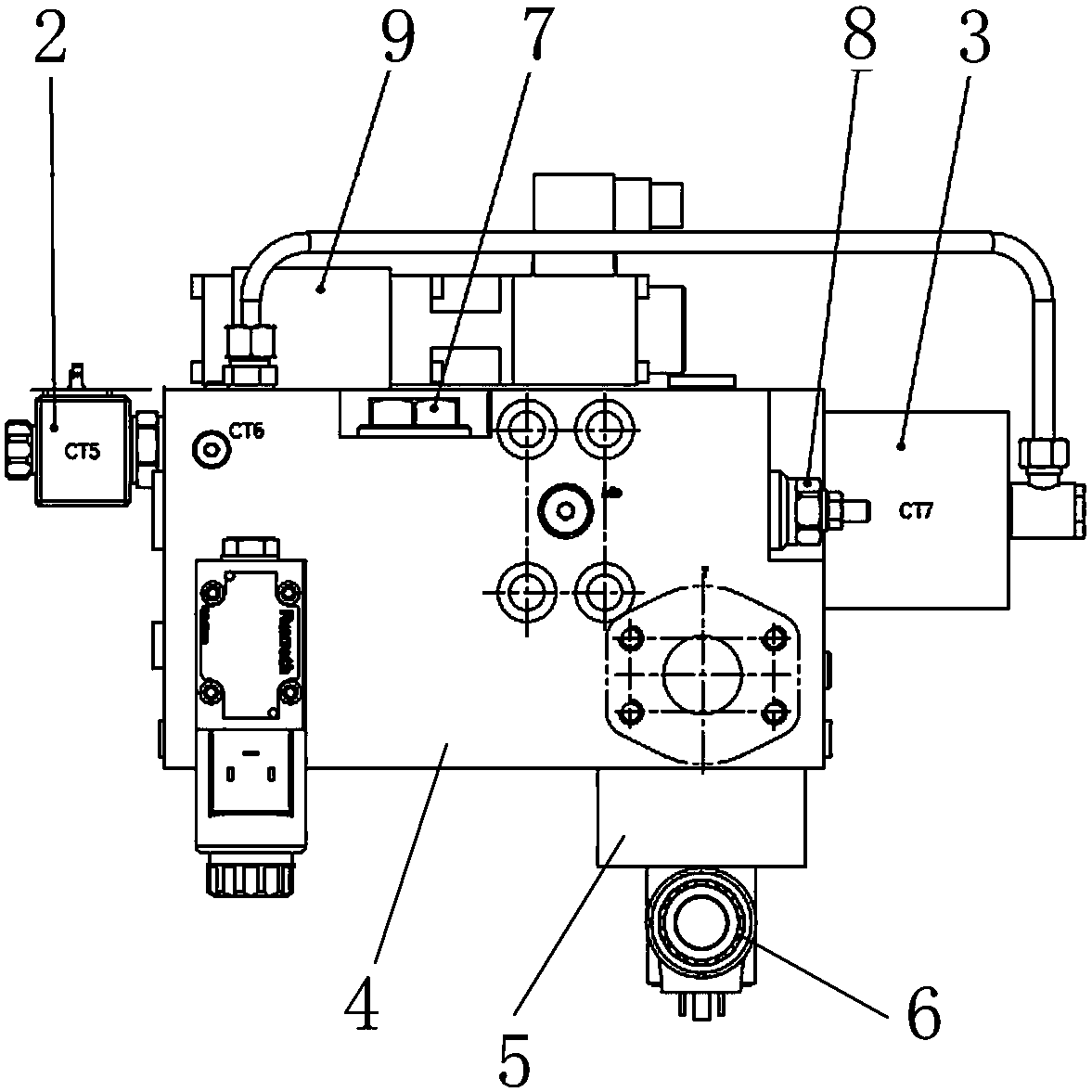
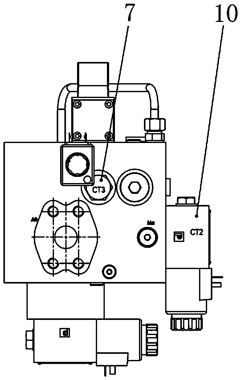
[0022] See attached figure 1 , figure 2 and image 3 Among them, a full hydraulic drilling rig suspension weight control valve group, including a valve block body 4, an electromagnetic reversing valve 10 is provided at the front end of the valve block body 4, and two-position four-way electric control reversing valves 2, 2 and 4 are respectively provided on both sides. The high-pressure relief valve 8 and the balance valve 3 are provided with an electromagnetic proportional relief valve 9 and a one-way valve 7 respectively at the top, and a two-way valve 6 and a cover valve 5 at the bottom. Four-way electric control reversing valve 2, high-pressure relief valve 8, balance valve 3, electromagnetic proportional relief valve 9, one-way valve 7, two-way valve 6 and cover valve 5 are all controlled by the electro-hydraulic control device, The valve block body 4 is installed at the B0 port of the lift-down pressure rodless cavity hydraulic cylinder, and the valve block body 4 has...


PUM


Abstract

The invention discloses a hanging load control valve bank of an all-hydraulic drill. The hanging load control valve bank of the all-hydraulic drill comprises a valve block body, wherein an electromagnetic reversing valve is arranged at the front end of the valve block body; an electronic control reversing valve, a high-pressure overflow valve and a balance valve are separately arranged on two sides of the valve block body; an electromagnetic proportional overflow valve and a one-way valve are separately arranged on the top of the valve block body; a two-way valve and a baffle valve are separately arranged at the bottom of the valve block body; the control valve bank is mounted at an oil inlet B0 of a rodless cavity of a lifting and pushing hydraulic cylinder; and functions of lifting, descending, pushing, hanging load, braking and the like of a drilling tool are fulfilled through a series of operations. Compared with the prior art, the hanging load control valve bank of the all-hydraulic drill is simple in structure and reasonable in design, conventional oil lines connected by pipelines are creatively modified into a plurality of plate valves and cartridge valves which are connected by the valve block body, the circumstances that the pipelines are exposed for a long time, oil leaks from connection joints and the like are avoided, during large well depth operation, requirements of pushing during shallow drilling can be met, and furthermore, hanging load during deep drilling can be realized.

Description

technical field [0001] The invention relates to the technical field of oil drilling rig equipment, in particular to a suspension weight control valve group of a full hydraulic drilling rig. Background technique [0002] In the field of oil drilling rig equipment, the lifting system is the core of the drilling rig. It is mainly used to control the drilling pressure and feed the drilling tools during the tripping of drilling tools, casing running and drilling, while the full hydraulic drilling rig mainly uses hydraulic cylinders as the core of the lifting system. The actuator, so the suspension weight control of the lifting and lowering hydraulic cylinder is particularly important. If the weight of the drill string is too large, the pressure exerted on the formation is too large, and the drill bit cannot drill. In this case, it is necessary to realize the suspended weight. At present, the hydraulic cylinder lifting system in the industry only installs a one-way balance valve a...

Claims


Application Information

Patent Timeline
Patent Type & Authority Patents(China)
IPC IPC(8): F15B13/02E21B3/02E21B19/08
CPCE21B3/02E21B19/08F15B13/02F15B2013/002F15B2013/004
Inventor 沈晓博张江河张金能马进生韩小启刘海伟华丹丹马向南
Owner RG PETRO MACHINERY GROUP
Learn More