
Desulfurization treatment system for flue gases in boiler in thermal power generating station

A boiler flue gas and treatment system technology, applied in the field of electric power, can solve the problems of surrounding corrosion and affecting the surrounding environment, and achieve the effect of reducing the cost of use and better cleaning effect

Inactive Publication Date: 2017-12-05
绵阳行之智汇知识产权服务有限公司
View PDF4 Cites 0 Cited by
  • Summary
  • Abstract
  • Description
  • Claims
  • Application Information

AI Technical Summary

Problems solved by technology

For the calcium method, "gypsum rain" will be formed, and for the ammonia method, "ammonia rain" will be formed. These flue gas condensate not only affect the surrounding environment, but also cause problems such as surrounding corrosion

Method used


Image

  • Desulfurization treatment system for flue gases in boiler in thermal power generating station
  • Desulfurization treatment system for flue gases in boiler in thermal power generating station
  • Desulfurization treatment system for flue gases in boiler in thermal power generating station

Examples


Embodiment 1

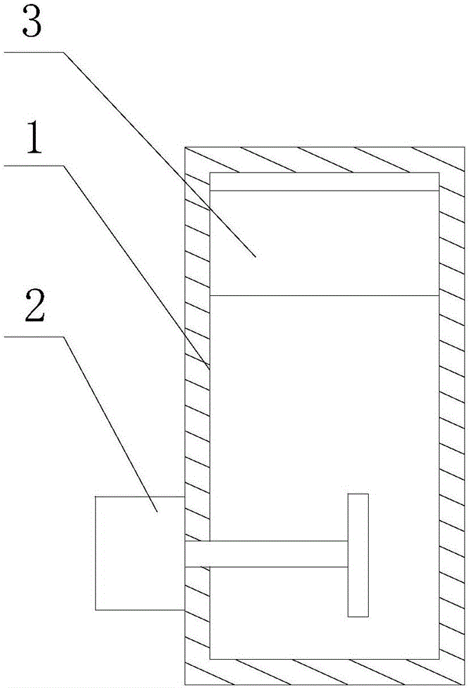
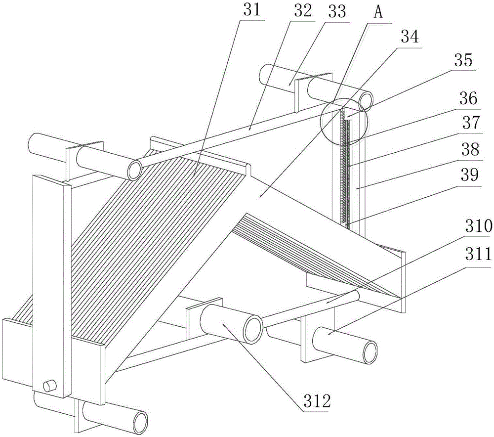
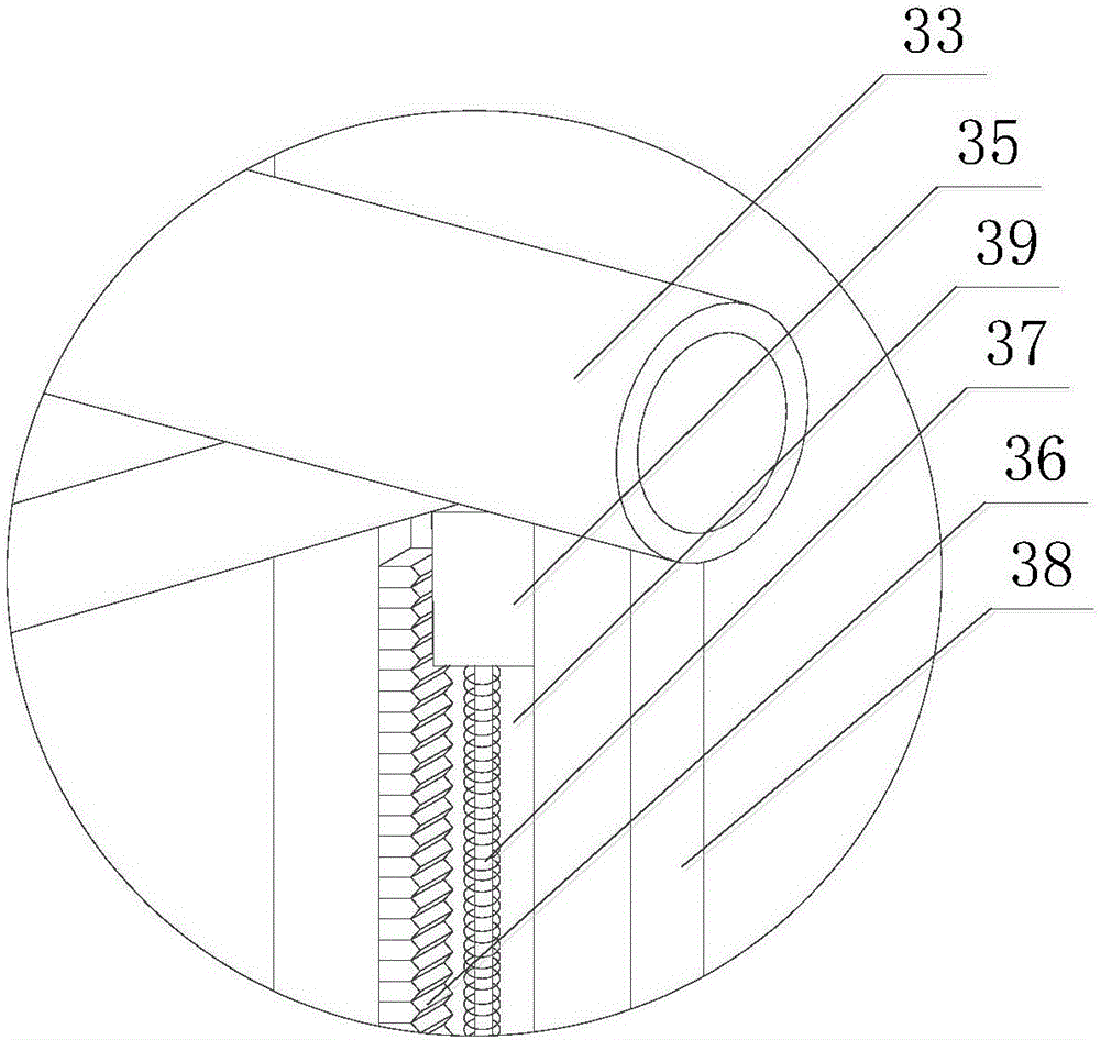
[0031] Such as Figure 1~5 As shown, this embodiment includes a tower body 1, a stirring assembly 2 and a demisting assembly 3, an air inlet and a liquid inlet are respectively opened on the side wall of the tower body 1, and an exhaust port is opened on the top of the tower body 1 The stirring assembly 2 is installed on the side wall of the tower body 1, the defogging assembly 3 is fixed on the inner top of the tower body 1, and the stirring assembly 2 includes a box body 1, a motor 23 and a fixed cylinder 24 arranged on the side wall of the box body 1 , the motor 23 is arranged on the fixed cylinder 24, and the output end of the motor 23 continues to extend after penetrating the side wall of the box body 1, and the driving wheel 22 is installed on the extension section of the output end of the motor 23, and the fixed cylinder 24 is far away from the box body A flange 27 is installed at one end of 1, and also includes a linkage shaft 216 disposed in the fixed cylinder 24 and ...

Embodiment 2

[0041] Such as figure 1 , 5 As shown, this embodiment further includes a sealing ring 210 disposed on the end surface of the extension section of the sleeve 28 , and the inner peripheral wall of the sealing ring 210 is in contact with the outer peripheral wall of the linkage shaft 26 . In the desulfurization tower, the blades 211 and part of the linkage shaft 26 are placed in the slurry, and the sleeve 28 is in a movable connection with the linkage shaft 26, that is, under the premise that the set seal ring 210 can ensure the normal rotation of the linkage shaft 26, the sleeve 28 and The connection gap of the linkage shaft 26 is sealed, that is, the inside of the sleeve 28 is isolated from the outside, so as to prevent slurry from entering the connection gap, thereby ensuring the normal rotation of the linkage shaft 26 .

[0042] Wherein, an annular groove is formed on the inner peripheral wall of the extension section of the sleeve 28, and a follower ring 29 matched with the...


PUM


Abstract

The invention discloses a desulfurization treatment system for flue gases in a boiler in a thermal power generating station. The system comprises a tower body, a stirring assembly, and a fog removing assembly, the side wall of the tower body is provided with a gas inlet and a liquid inlet, the top of the tower body is provided with an exhaust port, the stirring assembly is installed on the side wall of the tower body, and the fog removing assembly is fixed to the top of the interior of the tower body. According to the invention, the flue gases in the boiler are treated through the stirring assembly and the fog removing assembly in sequence, thus fog in upward-floating flue gases in the tower body can be fully adsorbed on the side walls of corrugated plates, flow quantity of the fog which is overflowed along a smoke vent is further reduced, and influences on surrounding environment caused by condensed water which is overflowed from the smoke vent of a chimney are reduced.

Description

technical field [0001] The invention relates to the field of electric power, in particular to a boiler flue gas desulfurization treatment system of a thermal power station. Background technique [0002] In the prior art, since the flue gas that has undergone wet scrubbing and desulfurization can be treated as saturated steam, its water content is relatively high. Even after demisting and dehydrating by two-layer demisters, it is easy to form " Chimney rain", especially for the desulfurization tower with integrated flue gas tower, after the flue gas is washed and deacidified by the desulfurization tower, it enters the chimney through the flue, and then is discharged into the atmosphere, while the desulfurization chimney mostly adopts a brick-cut structure with special anti-corrosion inside treatment, and the height of the chimney itself is more than 50 meters (required for environmental protection emissions), the cost is very high, and the cost of the chimney is even higher t...

Claims


Application Information

Patent Timeline
Patent Type & Authority Applications(China)
IPC IPC(8): B01D45/08B01D45/18
CPCB01D45/08B01D45/18
Inventor 王伟
Owner 绵阳行之智汇知识产权服务有限公司
Learn More