Coordinate measuring machine, probing system and method for compensating force at probe element

A technology of coordinate measuring machine and detection system, which is applied in the force field of coordinate measuring machine, detection system and compensating probe elements, to avoid cross-coupling

Inactive Publication Date: 2016-06-29
HEXAGON TECH CENT GMBH
View PDF8 Cites 14 Cited by
  • Summary
  • Abstract
  • Description
  • Claims
  • Application Information

AI Technical Summary

Problems solved by technology

Due to the passive nature of existing probes (using viscous fluids), a

Method used


Image

  • Coordinate measuring machine, probing system and method for compensating force at probe element
  • Coordinate measuring machine, probing system and method for compensating force at probe element
  • Coordinate measuring machine, probing system and method for compensating force at probe element

Examples


Embodiment approach

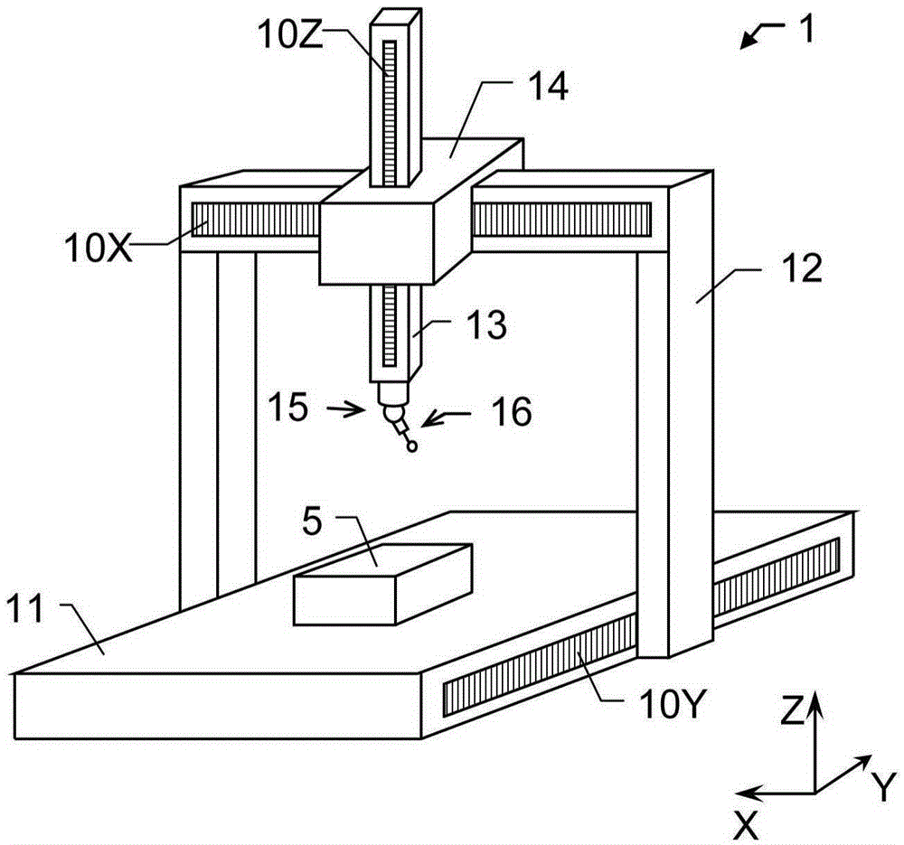
[0112] exist figure 1 In, an exemplary embodiment of a gantry coordinate measuring machine 1 (CMM) according to the present invention is depicted, the coordinate measuring machine 1 comprising a base 11 and a frame structure for connecting a probe 15 and a device connected to the probe 15. The detection unit 16 is coupled to the base 11, said frame structure comprising several frame parts 12, 13, 14 movable relative to each other. The first frame part 12 is a mast having two mast legs connected by a bridge portion at their upper ends. Driven by a drive mechanism (not shown), the frame part 12 is movable along the longitudinal edge of the base 11 . This direction corresponds to the first direction Y. The movement of the frame part 12 is in particular via a toothed rack attached to the base 11 , which meshes with a gear on the frame part 12 .

[0113] Brackets 14 are movably arranged on bridge portions 12 between the frames. The movement of the carriage 14 (the carriage 14 i...


PUM


Abstract

The invention a coordinate measuring machine, a probing system and a method for compensating a force at a probe element. A probing unit (16) comprises an actuator (21) which is arranged and designed in such manner that a force is applicable to the probe element with respect to at least one actuating direction in variable and defined manner, the force depending on an applied actuating signal. Movement information about an expected movement of the probing unit (16) is received, the movement information provides information about an expected displacement behaviour of the probe element relative to the probing unit due to induced forces emerging by moving the probing unit (16). At least one particular expected displacement behaviour of the probe element is derived for at least one particular moving point based on the movement information and the actuating signal is determined for the at least one particular moving point based on the at least one particular expected displacement behaviour, the actuating signal provides applying a defined counterforce to the probe element by the actuator (21) as to the expected displacement behaviour at the particular moving point.

Description

technical field [0001] The present invention generally relates to a method for compensating or avoiding effects on a stylus element of a Coordinate Measuring Machine (CMM) which are believed to arise due to moving the stylus element according to a given measurement path. Background technique [0002] In order to check predetermined object parameters, such as the size and shape of the object, it is common practice to inspect the workpiece after production on a coordinate positioning device such as a coordinate measuring machine (CMM). [0003] In a conventional 3D coordinate measuring machine, the probe is supported for movement along three mutually perpendicular axes (in directions X, Y and Z). In this way, the probe can be guided to any point in the space of the measurement volume of the coordinate measuring machine, and the object can be measured with the measuring sensor (probe unit) carried by the probe. [0004] In a simple form of a coordinate measuring machine, suita...

Claims


Application Information

Patent Timeline
IPC IPC(8): G01B21/04
CPCG01B21/04G01B21/047G01B5/008G01B7/008G01B11/005G01B3/008G01B21/045
Inventor C·艾斯利伯恩哈德·施普伦格
Owner HEXAGON TECH CENT GMBH
Why Eureka
Try Eureka