Chuck-type wing loading device

A loading device and chuck-type technology, which is applied in the field of chuck-type wing loading devices, can solve problems such as damage, inaccurate equipment weight deduction, and excessive clamping load applied to the wing.

Active Publication Date: 2016-06-29
CHINA AIRPLANT STRENGTH RES INST
View PDF7 Cites 12 Cited by
  • Summary
  • Abstract
  • Description
  • Claims
  • Application Information

AI Technical Summary

Problems solved by technology

In this rigid pallet loading device, the machining error of the four loading wooden blocks on the wing surface is compensated by the vertical deformation of the wing after the rigid pallet is installed, and it is easy to apply an excessive clamping load to the wing, resulting in The local pressure of the wing is destabilized or even destroyed; on the other hand, the rigid clamp loading device increases the vertical stiffness of the wing section, which actually strengthens the wing section structure and changes the load-bearing characteristics and transmission characteristics of the wing structure. The...

Method used


Image

  • Chuck-type wing loading device
  • Chuck-type wing loading device
  • Chuck-type wing loading device

Examples


Embodiment Construction

[0029] Specific embodiments of the present invention will be further described in detail below.

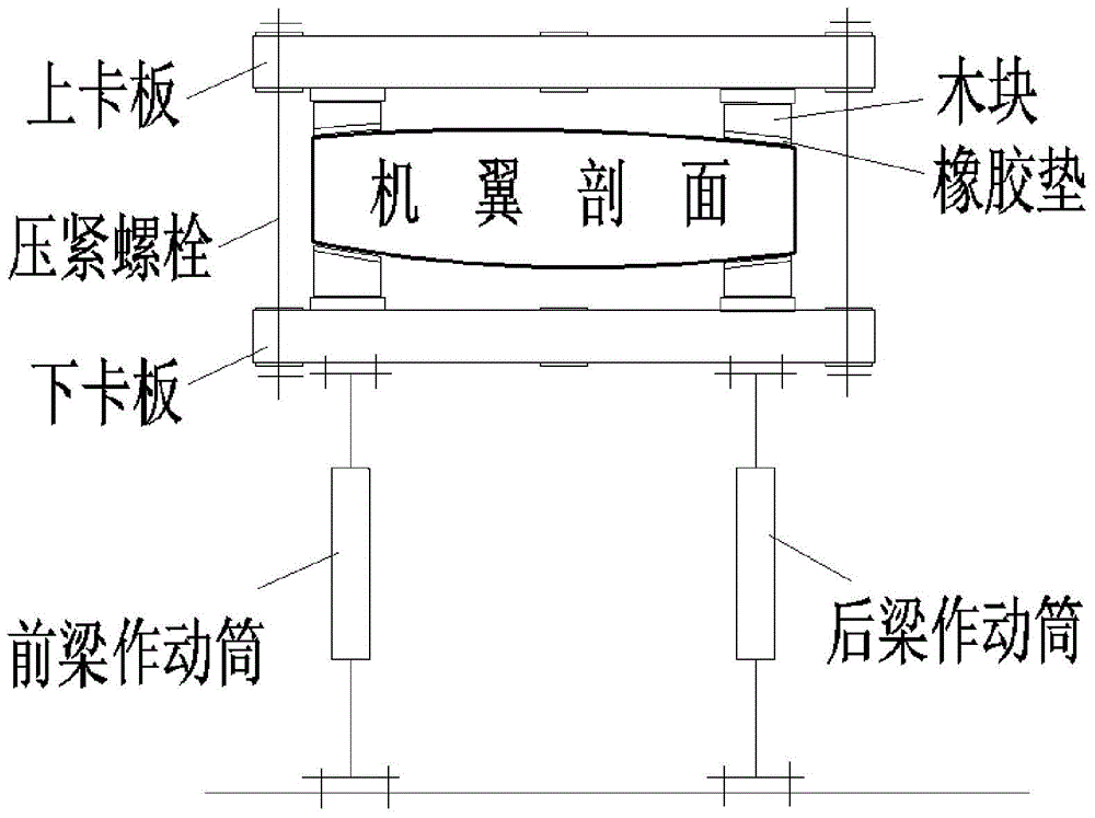
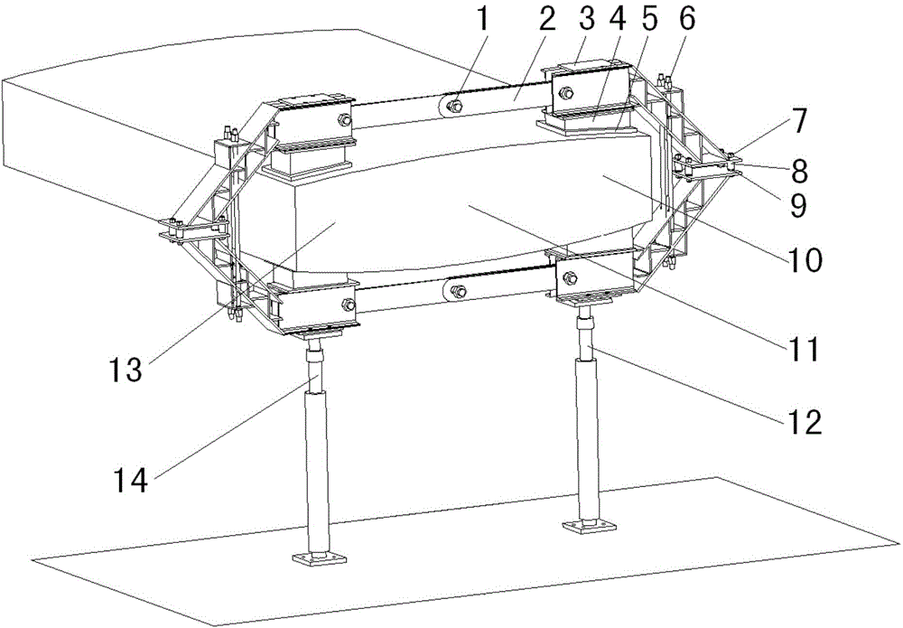
[0030] see figure 2 , the chuck type wing loading device of the present invention comprises a pull plate bolt 1, a pull plate 2, a loading chuck 3, a loading block 4, a square rubber pad 5, a chuck pressing bolt 6, a chuck connecting bolt 7, a bushing 8. Spring washer 9, rear beam 10, wing section 11, rear beam actuator 12, front beam 13 and front beam actuator 14.

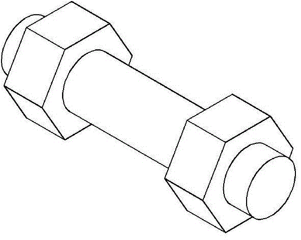
[0031] Wherein, the tie plate bolts are standard parts, the material is usually 45 steel, and the quantity is 6 pieces, such as image 3 As shown, it is used to connect the pull plate to the pull plate, and also to connect the pull plate to the loading chuck.

[0032] Labanru Figure 4 As shown, it is processed by steel plate, the material is usually Q235 steel, the quantity is 6 pieces, and it is used to connect the loading chuck at the position of the front and rear beams.

[0033] Load the chuck as Figure 5 ...


PUM


Abstract

The invention belongs to the aircraft strength test technology, and relates to a chuck-type wing loading device, which includes a pulling plate bolt, a pulling plate, a loading chuck, a loading wood block, a square rubber pad, a chuck compression bolt, a chuck connecting bolt, a bush, a spring washer, a rear spar, a wing profile, a rear spar actuator cylinder, a front spar and a front spar actuator cylinder. The invention is solid in mounting, the test load is accurately applied, the front spar load applying and the rear spar load applying are not influenced by each other, the device weight is accurately deducted, and the device does not increase the vertical stiffness of the wing profile.

Description

technical field [0001] The invention belongs to the aircraft strength test technology, and relates to a chuck type wing loading device. Background technique [0002] In the aircraft structural strength test, especially the fatigue test, the wing load is usually processed to the position of the front and rear beams of the wing, and is applied through the actuator installed on the lower wing surface. The loads at the position of the front and rear beams of the wing have three situations: simultaneous upward, simultaneous downward, and one up and one down. When the wing load is upward, the actuating cylinder is extended and applied, and the actuating cylinder bears the compressive load. When the wing load is downward, the actuating cylinder is contracted and applied, and the actuating cylinder bears the tensile load. [0003] The most effective wing loading device at this stage is a rigid pallet loading device, such as figure 1 As shown, firstly, glue the rubber plate and the...

Claims


Application Information

Patent Timeline
IPC IPC(8): G01M13/00
Inventor 臧伟锋苏少普许飞董登科
Owner CHINA AIRPLANT STRENGTH RES INST
Why Eureka
Try Eureka