
Optimizing method for five-axis numerical control machining singular region cutter location point
A technology of singular area and optimization method, applied in the direction of digital control, program control, electrical program control, etc., can solve the problems of large error and unsatisfactory machining accuracy, and achieve the effect of preventing overcut, shortening machining time, and improving machining efficiency.
- Summary
- Abstract
- Description
- Claims
- Application Information
AI Technical Summary
Problems solved by technology
Method used
Image

Examples
Embodiment 1
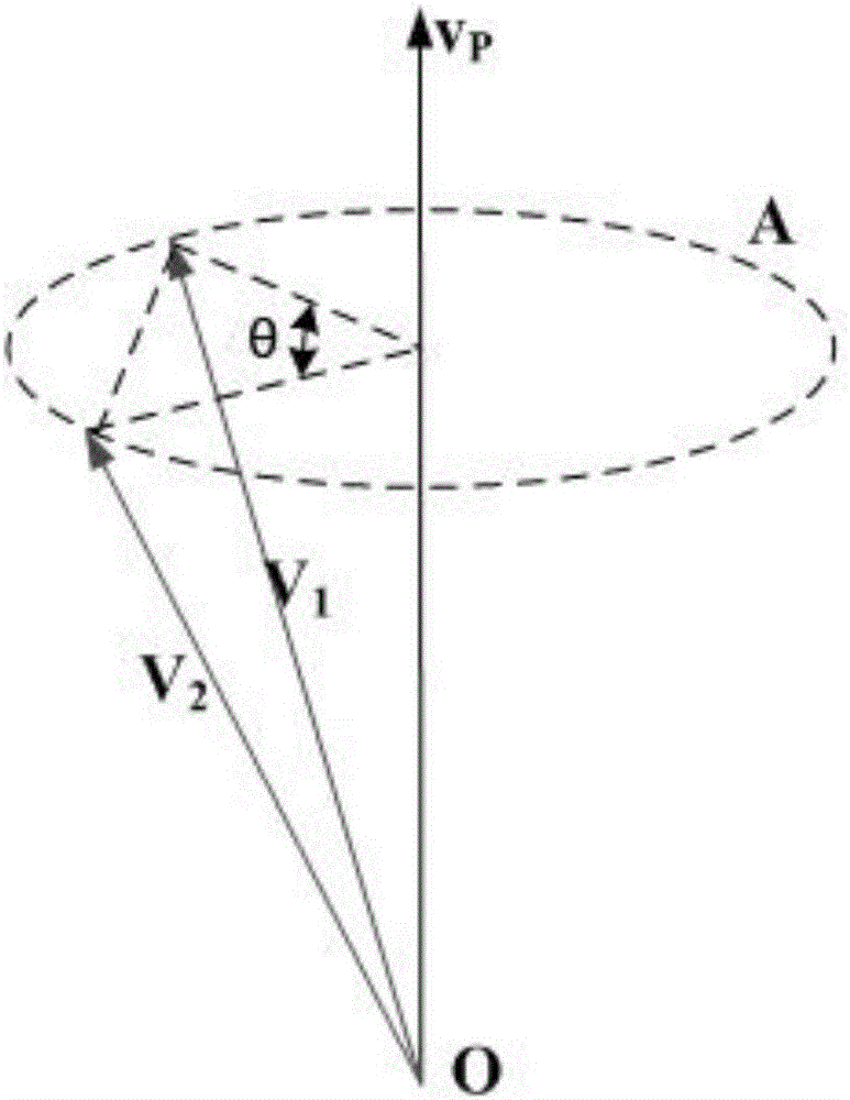
[0050] First, in order to facilitate the understanding of the problems in the singular region, a geometric model of the singular region is established, such as figure 1 shown.
[0051] figure 1Among them, V1 represents the start vector of the tool axis, V2 represents the end vector of the tool axis, θ represents the angle between the start vector of the tool axis and the end vector of the tool axis on the projection plane, O represents the origin, Vp represents the polar axis, and Vp As the axis, take the V1 and V2 vectors as the generatrices to make a cone-shaped space, and the projection to the plane is the circle A.
[0052] When the angle between V1, V2 and the polar axis Vp is small, even if the angle between V1, V2 is small, the angle θ of their projections on the plane with the polar axis Vp as the normal vector may be very large, This is the fundamental reason why the spindle of the machine tool still needs to swing a lot even though the swing angle on the same sur...
Embodiment 2
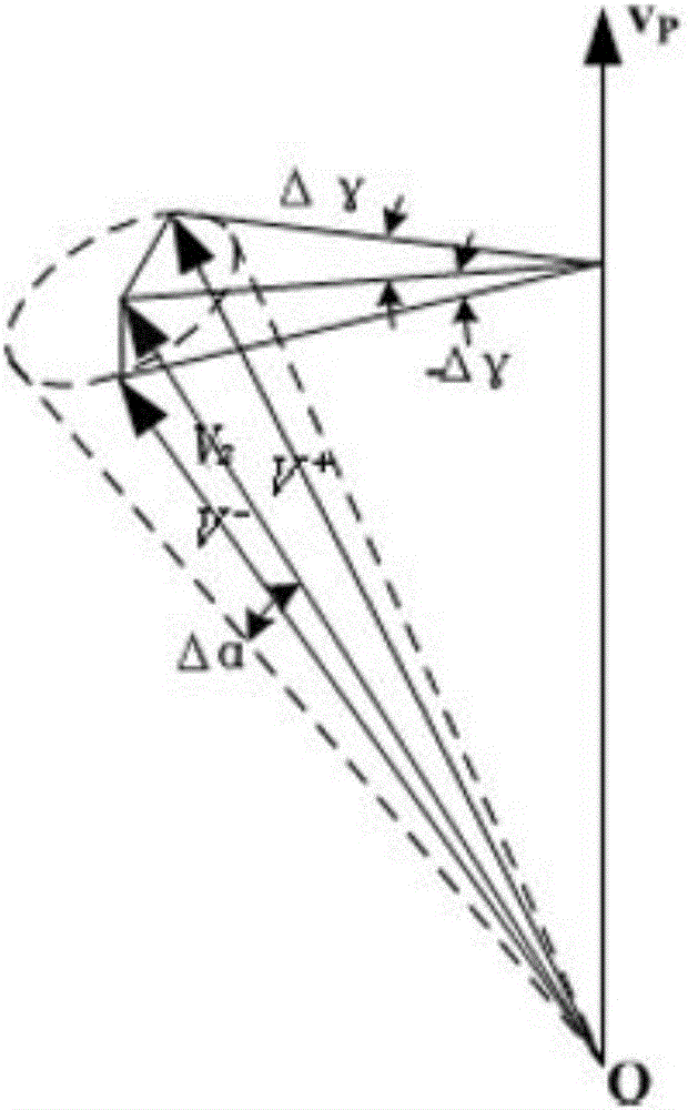
[0059] The difference with embodiment 1 is only: when the polar axis is outside the neighborhood of the tool axis end vector, establish as figure 2 The mathematical model for tool path optimization is shown.
[0060] figure 2 , to be optimized vector V 2 is the center line, the origin O is the apex, and the tolerance Δα is the half-vertex angle to form a conical space. All the generatrices of the conical space and the vector V 2 The included angles are Δα. Through the polar axis Vp, two planes are tangent to the conical surface, and the tangent vectors formed are respectively used by the vector V - and V + express.
[0061] vector V - and V + The angles projected on the plane where the polar axis Vp is the normal vector are Δγ and -Δγ respectively. After the vector V to be optimized 2 with V - and V + Two planes p' and p" are made respectively, and the vector of the previous tool axis is used as the optimization target vector of the current tool axis, and the opti...
Embodiment 3
[0068] Embodiment 1 and embodiment 2 are the optimization methods that the tool axis ends up in the vector under two different situations, especially the optimization method in embodiment 2, because the mathematical expression is used to find V - and V + Relatively complex, in order to better realize the present invention, the applicant transformed it into a mathematical expression for further disclosure.
[0069] Known: optimize the target vector v 1 =(i 1 j 1 k 1 ), the vector to be optimized v=(ijk), the polar axis vector v p =(i p j p k p ), tolerance Δα.
[0070] Seek: Optimize the tool axis vector v y =(i'j'k'), so that the angle between the tool axis vector after optimization and the vector to be optimized (v p v)y v 1 v p ) | min.
[0071] Through the above analysis, the mathematical model of tool path optimization can be simplified into a ternary quadratic equation system:
[0072] ...
PUM
 Abstract
Description
Claims
Application Information