
Display device

A technology for a display device and a display panel, which is applied to an identification device, a casing with a display/control unit, optics, etc., can solve the problems of reducing the screen ratio of the display device, time-consuming and laborious assembly process, and increasing the thickness of the display device, etc. Achieve the effect of improving assembly efficiency, reducing workload, and achieving good visual experience.

Active Publication Date: 2016-06-29
HISENSE VISUAL TECH CO LTD
View PDF10 Cites 5 Cited by
  • Summary
  • Abstract
  • Description
  • Claims
  • Application Information

AI Technical Summary

Problems solved by technology

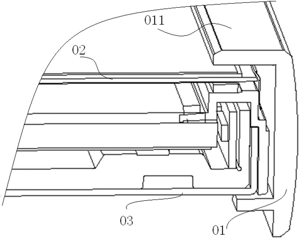
[0007] However, the bezels of display devices with ultra-narrow bezels currently on the market are mostly U-shaped, such as figure 1 As shown, the U-shaped frame 01 snaps together the various components in the display device, which makes the edges of the display panel 02 covered with a frame 011, thereby reducing the screen ratio of the display device and increasing the Display device thickness
At the same time, the U-shaped frame 01 needs to be fixedly connected with components such as the back plate 03 by screws to ensure the stability of the display device, which requires that the threaded holes on each component must be aligned during assembly, thereby increasing the Assembly is difficult, and the assembly process is time-consuming and laborious, which reduces assembly efficiency

Method used


Image

  • Display device
  • Display device
  • Display device

Examples


Embodiment Construction

[0019] The following will clearly and completely describe the technical solutions in the embodiments of the present invention with reference to the accompanying drawings in the embodiments of the present invention. Obviously, the described embodiments are only some of the embodiments of the present invention, not all of them. Based on the embodiments of the present invention, all other embodiments obtained by persons of ordinary skill in the art without making creative efforts belong to the protection scope of the present invention.

[0020] In describing the present invention, it is to be understood that the terms "center", "upper", "lower", "front", "rear", "left", "right", "vertical", "horizontal", The orientations or positional relationships indicated by "top", "bottom", "inner", "outer", etc. are based on the orientations or positional relationships shown in the drawings, and are only for the convenience of describing the present invention and simplifying the description, ...


PUM


Abstract

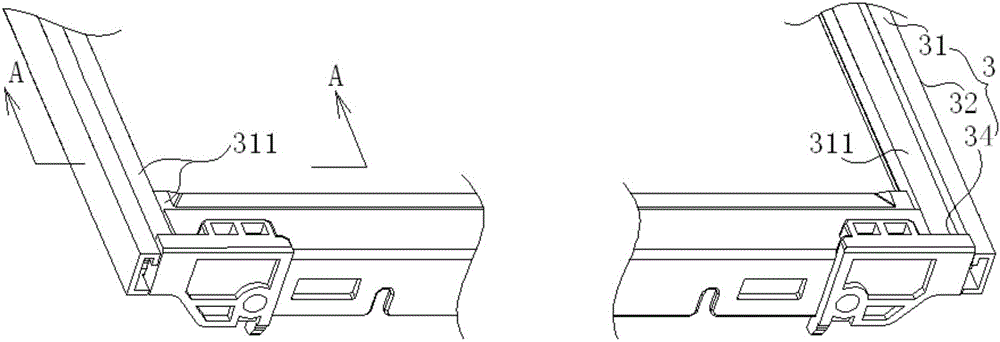
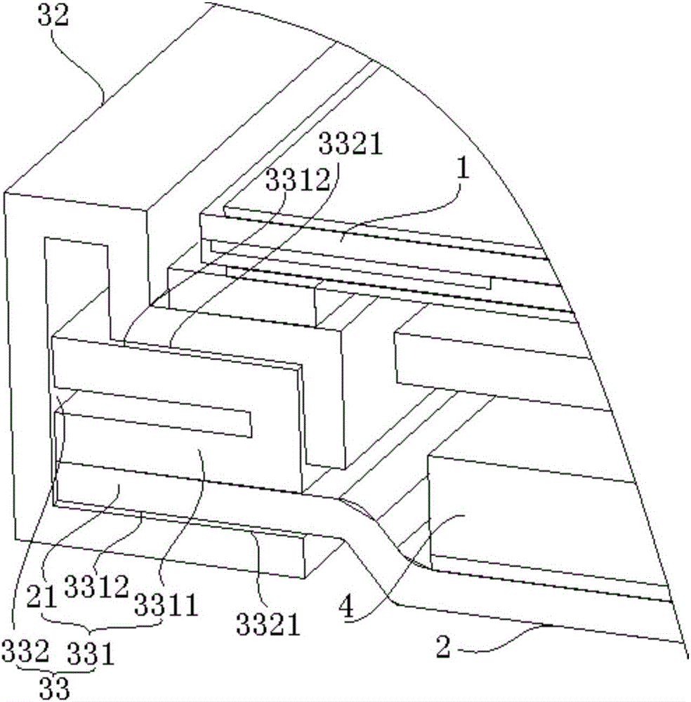
The embodiment of the invention provides a display device, relating to the technical field of electronic equipment. According to the display device, the problems of small screen ratio, large thickness, high assembling difficulty and low efficiency of existing display devices are solved. The display device comprises a display panel, a backboard and a side frame, wherein a sink table for fixing the display panel is formed in the front surface of the side frame; the side frame is surrounded by four strip-shaped side frames, three strip-shaped side frames are inserted into three edges of the backboard along the direction parallel to the edges of the backboard by virtue of an insertion structure, the other strip-shaped side frame is fixedly connected with the other edge of the backboard, and the insertion structure is capable of limiting the movement of the inserted strip-shaped side frames along the direction vertical to the display panel and limiting the movement of the inserted strip-shaped side frames along the direction vertical to the insertion direction in a plane parallel with the display panel; and limiting structures are formed in splicing parts of the strip-shaped side frames and are capable of limiting the movement of the inserted strip-shaped side frames along the insertion direction. The display device is used for displaying images.

Description

technical field [0001] The present invention relates to the technical field of electronic equipment, in particular to a display device. Background technique [0002] With the continuous development of science and technology and the continuous improvement of people's living standards, products with display devices such as televisions and computers have become necessary electronic products for every family. Increase, users will not only consider the performance of the product when choosing, but also factors such as price, appearance (volume, aesthetics, etc.) and weight will also affect the user's choice of products. [0003] At present, the main development trend of display devices is to develop in the direction of ultra-narrow bezels, and ultra-narrow bezel display devices have the following advantages: [0004] 1. The ultra-narrow bezel effectively increases the screen-to-body ratio and realizes an ultra-wide video screen. Users have a wider field of vision when watching a...

Claims


Application Information

Patent Timeline
IPC IPC(8): G09F9/00G02F1/1333H05K5/00
CPCG02F1/133308G09F9/00H05K5/0017
Inventor 王慧马吉航
Owner HISENSE VISUAL TECH CO LTD
Learn More