
Composite resonance sound absorption structure

A resonant sound-absorbing and sound-absorbing technology, which is applied in the direction of sound-emitting devices, instruments, and layered products, can solve problems such as the inability to realize the processing of micro-perforated plates with ultra-micro-pore diameters, unsuitable for mass production, and poor sound-absorbing effects. Achieve the effect of good sound absorption effect, low price and easy processing

Pending Publication Date: 2016-06-29
BEIJING MUNICIPAL INST OF LABOUR PROTECTION
View PDF12 Cites 8 Cited by
  • Summary
  • Abstract
  • Description
  • Claims
  • Application Information

AI Technical Summary

Problems solved by technology

However, this structure also has its inherent disadvantages. The main disadvantage is that the frequency selectivity is strong, that is, its sound absorption frequency band is narrow, and it only has good sound absorption performance near the resonance frequency, and it deviates from the resonance frequency. Its sound absorption effect is significantly worse
However, traditional mechanical processing methods cannot realize the processing of micro-perforated plates with ultra-micro-pore diameters. Other processing methods such as laser drilling will greatly increase the production cost due to the increase in drilling density, which is not suitable for mass production.

Method used


Image

  • Composite resonance sound absorption structure
  • Composite resonance sound absorption structure
  • Composite resonance sound absorption structure

Examples


Embodiment 1

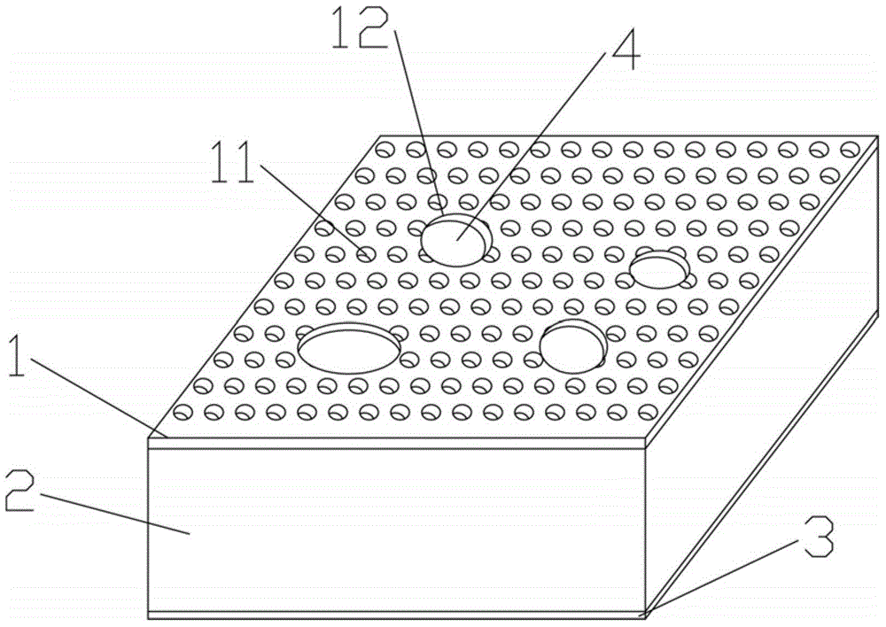
[0024] refer to figure 1 As shown, the composite resonance sound-absorbing structure includes: a bottom plate 3, a side wall 2 and a cover plate 1, the cover plate 1 and the bottom plate 3 are relatively spaced apart, and the side walls 2 are closely connected with the bottom plate 3 and the cover plate 1 respectively to form a sound-absorbing back cavity. The depth of the sound-absorbing back cavity is 5-80mm, preferably 5mm, 10mm, 15mm, 20mm, 50mm or 80mm. The cross section of the side wall 2 is a closed structure, preferably in the shape of "O", "mouth" or "Tian". refer to figure 1 As shown, the bottom plate 3 and the cover plate 1 are arranged in parallel, the side wall 2 is perpendicular to the bottom plate 3 and the cover plate 1, and the two ends of the side wall 2 are closely connected with the bottom plate 3 and the cover plate respectively, forming one or more sound-absorbing back cavity. The cover plate 1 is provided with a plurality of micro sound absorption ho...

Embodiment 2

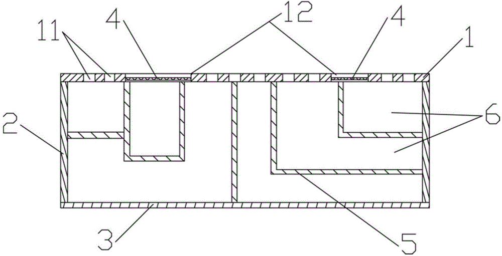
[0032] This embodiment is basically the same as Embodiment 1, the difference is: refer to image 3 As shown, the composite resonance sound-absorbing structure also includes a partition plate 5; the partition plate 5 is closely attached to the inner wall of the cover plate 1, the bottom plate 3 and / or the side wall 2, and divides the sound-absorbing back cavity into a plurality of independent absorbing Acoustic chambers 6 ; each sound-absorbing chamber 6 communicates with micro-sound-absorbing holes 11 and / or composite sound-absorbing holes 12 . The partition plate 5 divides the sound-absorbing back cavity into multiple sound-absorbing chambers 6, and the depths of the multiple sound-absorbing chambers 6 are not exactly the same. vertical height. The number of partitions 5 is multiple, and the shapes of the partitions 5 can be various, so that the sound absorption chamber 6 is a cuboid, cylinder, cone or irregular body and the like. Sound waves flow into the sound-absorbing c...


PUM

PropertyMeasurementUnit
diameteraaaaaaaaaa

Abstract

The invention relates to the technical field of sound absorption plates, and discloses a composite resonance sound absorption structure. The structure comprises a bottom plate, side walls, and a cover plate. The cover plate and the bottom plate are arranged at an interval in an opposite manner. The side walls are respectively in tight connection with the bottom plate and the cover plate, thereby forming a sound absorption back cavity. The cover plate is provided with a plurality of miniature sound absorption holes and a plurality of composite sound absorption holes. Each composite sound absorption hole is provided with one sound absorption diaphragm. The cover plate is provided with the plurality of composite sound absorption holes, and the sound absorption holes are provided with the sound absorption diaphragms in a pasted manner, thereby enlarging the sound absorption bandwidth of the structure. The structure is easy to machine, is low in cost, is convenient to install, and is good in sound absorption effect.

Description

technical field [0001] The invention relates to the technical field of sound-absorbing panels, in particular to a composite resonance sound-absorbing structure. Background technique [0002] The traditional perforated plate resonant absorption structure has a closed cavity behind each hole on the perforated plate, which is equivalent to many parallel "Helmholtz" resonators. When the frequency of the incident wave is consistent with the resonance frequency of the system, that is resonate. At this time, the reciprocating vibration of the air at the hole of the perforated plate reaches the maximum amplitude, and the friction and damping are also the maximum, and the sound energy is converted into heat energy due to viscous loss, that is, the sound energy dissipation reaches the maximum. This is the advantage of the perforated plate resonant absorption structure. However, this structure also has its inherent disadvantages. The main disadvantage is that the frequency selectivit...

Claims


Application Information

Patent Timeline
Patent Type & Authority Applications(China)
IPC IPC(8): G10K11/168G10K11/172B32B3/10
Inventor 盖晓玲李贤徽张斌马智慧王文江刑拓
Owner BEIJING MUNICIPAL INST OF LABOUR PROTECTION
Learn More