Anti-theft locking device of power transformer

A technology of power transformers and locking devices, which is applied in the direction of circuit devices, transformer/reactor installation/support/suspension, electrical components, etc., can solve the problems of limited anti-theft effect and electronic monitoring anti-theft technology cannot be effectively prevented, and achieve structural simple effect

Active Publication Date: 2016-06-29
国网黑龙江省电力有限公司双鸭山供电公司 +3
View PDF6 Cites 3 Cited by
  • Summary
  • Abstract
  • Description
  • Claims
  • Application Information

AI Technical Summary

Problems solved by technology

[0006] The purpose of the present invention is to provide an anti-theft locking device for power transformers in order to solve the problems that the mechanical anti-theft effect of power transformers is limited and the electronic monitoring anti-theft technology cannot effectively prevent thieves from on-site theft.

Method used


Image

  • Anti-theft locking device of power transformer
  • Anti-theft locking device of power transformer
  • Anti-theft locking device of power transformer

Examples


specific Embodiment approach 1

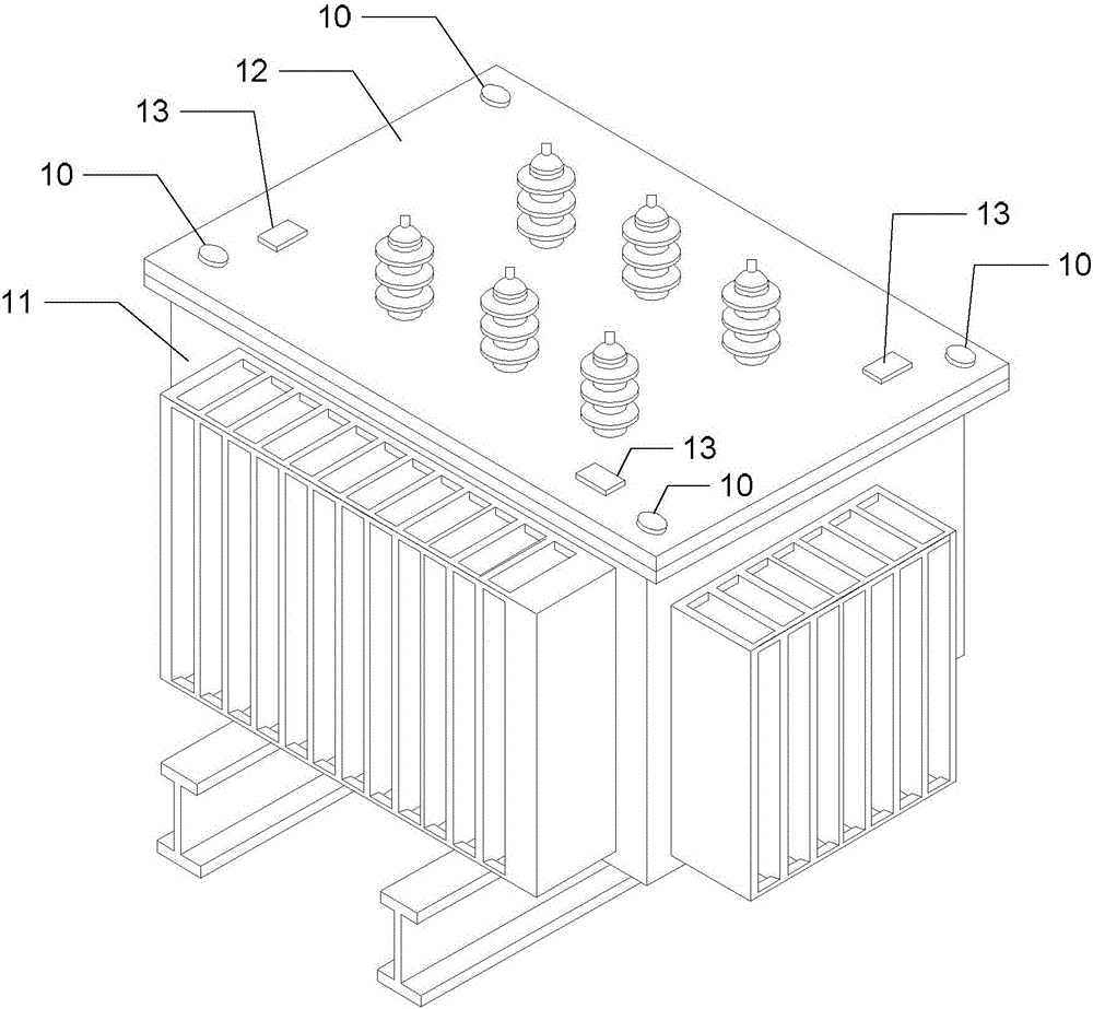
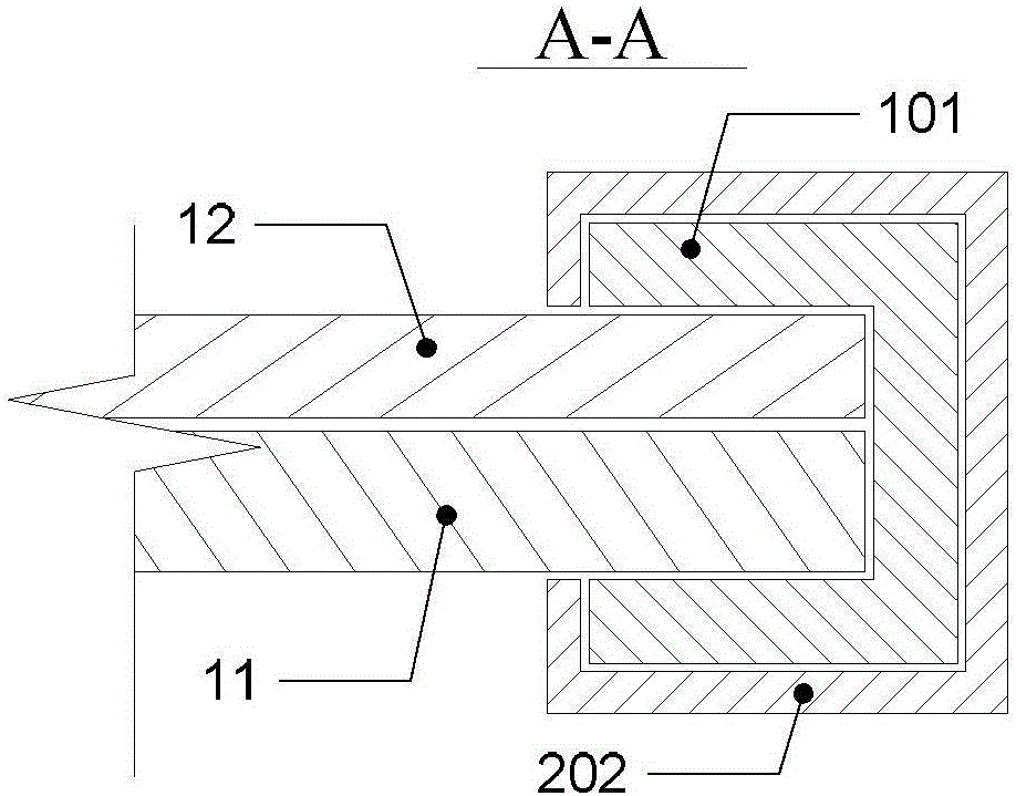
[0039] Specific implementation mode one: the following combination Figure 1 to Figure 17 Describe this embodiment, the anti-theft locking device of the power transformer described in this embodiment, the transformer casing 11 and the transformer upper cover 12 are connected by a bolt and nut structure 10; the transformer upper cover 12 is a rectangular plate structure, and the quadrilateral shape of the rectangular plate The three corners are provided with bolt and nut structures 10;

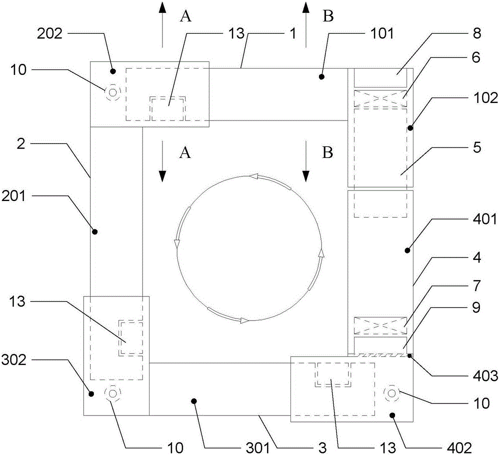
[0040] The anti-theft locking device includes No. 1 L-shaped locking plate 1, No. 2 L-shaped locking plate 2, No. 3 L-shaped locking plate 3, No. 4 L-shaped locking plate 4, locking bolt plate 5, No. 1 electromagnet 6, and No. 2 Electromagnet 7, No. 1 control unit 8, No. 2 control unit 9, three locking blocks 13, main control unit 14 and hand-held wireless remote control switch 15;

[0041] A locking block 13 is fixed near each bolt and nut structure 10 on the transformer upper cover 12;

[0...

specific Embodiment approach 2

[0066] Specific implementation mode two: the following combination Figure 16 with Figure 17 Describe this embodiment, this embodiment will further explain Embodiment 1, the main control unit 14 includes a main controller 14-1, a wireless energy transmission unit 14-2 and a main control wireless communication unit 14-3; the main controller 14-1 The alternating current provided by the transformer is used as the working power supply;

[0067] No. 1 control unit 8 includes No. 1 controller 8-1, No. 1 wireless energy receiving unit 8-2, No. 1 storage battery 8-3, No. 1 power detection unit 8-4 and No. 1 wireless communication unit 8-5; No. battery 8-3 provides operating power for No. 1 controller 8-1 and No. 1 electromagnet 6, and No. 1 controller 8-1 controls the switch of No. 1 electromagnet 6; No. 1 controller 8-1 passes through No. 1 power The detection unit 8-4 detects the power of the No. 1 storage battery 8-3. When the power is insufficient, the No. 1 controller 8-1 perf...


PUM


Abstract

An anti-theft locking device of a power transformer belongs to the field of a power system, which is used for solving the problems that the mechanical anti-theft effect of an existing power transformer is limited and an electronic monitoring anti-theft technology cannot be used for effectively preventing a site theft behavior of a thief. In the scheme, a first L-shaped locking plate, a second L-shaped locking plate, a third L-shaped locking and a fourth L-shaped locking plate are used for sequentially clamping a transformer shell and four side edges of an upper cover of the transformer, a locking bolt plate is used for locking or opening the fourth L-shaped locking plate and the first L-shaped locking plate from inside, the locking bolt is controlled to move through on-off of two groups of electromagnets, power is supplied to the electromagnets by a storage battery, and the storage battery adopts a wireless mode to charge. In the locking device, weak bolt and nut structures are packaged, the locking device forms a round locking force, an attack force which can be resisted is very large, the locking device cannot be forcedly opened through a small-sized tool by the thief, and perfect anti-theft protection on a field power transformer is achieved.

Description

technical field [0001] The invention relates to the field of power systems. Background technique [0002] Transformers are important equipment in the power system and play a vital role in the transmission and distribution of electric energy. However, many power transformers are installed in the open outdoors and use unattended mode. There are often thefts during operation. Risk, some criminals destroy and steal transformers, and sell the copper core coils as scrap copper to make a profit. The destruction and the theft of copper coils caused huge losses to national property and industrial and agricultural production. Therefore, the safety protection of power transformers is an urgent problem to be solved by the power sector. [0003] At present, the anti-theft technology for transformers is mainly divided into two categories: one is the mechanical structure, and the other is the electronic monitoring remote alarm module. [0004] The first type of anti-theft technology mai...

Claims


Application Information

Patent Timeline
Patent Type & Authority Applications(China)
IPC IPC(8): H01F27/06H02J13/00
CPCH01F27/06H02J13/0006
Inventor 唐彪刘海波于晓刚陈国江
Owner 国网黑龙江省电力有限公司双鸭山供电公司
Why Eureka
Try Eureka