Aligning apparatus for image module and application method thereof

An image module and core-alignment technology, which is applied in image communication, television, electrical components, etc., can solve problems such as the alignment of the lens module and the photosensitive chip, the inability of the image module to produce a clear image, vibration and dust interference, etc.

Active Publication Date: 2016-06-29
NINGBO SUNNY OPOTECH CO LTD
View PDF4 Cites 30 Cited by
  • Summary
  • Abstract
  • Description
  • Claims
  • Application Information

AI Technical Summary

Problems solved by technology

In the common manual production mode, the assembly of the image module is to manually adjust the positions of the lens assembly (VCM) and the photosensitive chip (SENSOR) in the image module, so that the lenses and filters installed in the lens assembly The geometric optical axis center of the optical lens is aligned with the center of the photosensitive element of the image module. However, the lens and photosensitive chip may cause the optical center to shift when the system is assembled in such axisymmetric optical components due to operational errors. There are positional accuracy deviations such as tilt (Tilt) and shift (Shift) between the lens and the photosensitive chip, which have a serious impact on the imaging quality of the module, resulting in a continuous decline in product yield
[0004] At present, the packaging process (COB) of the mobile phone camera module and related optical components industry generally adopts the lens holder attachment (H / A) to fix the finished product, and the lens holder attachment adopts the glue to directly stick In the attached way, the lens module is assembled with the photosensitive chip, and because the geometric optical axis center of the optical lens of the lens module and the aperture center of the lens holder usually have deviations, it is difficult to accurately make the lens module and the photosensitive chip relatively by manual operation. The unsatisfactory alignment effect will directly affect the focus test of the subsequent finished product, resulting in the inability of the image module to produce a clear picture
In addition, the centering, testing and dispensing process of the imaging module needs to be replaced with different operating tables during the manufacturing process, and there is a process of moving the imaging module, which may cause vibration and dust interference in the imaging module. risk, reducing the quality of the image module, and in order to increase the accuracy of the alignment, the size of the image module is difficult to reduce. Once the image module with a smaller size is produced, it poses a greater challenge to the COB process and alignment operation

Method used


Image

  • Aligning apparatus for image module and application method thereof
  • Aligning apparatus for image module and application method thereof
  • Aligning apparatus for image module and application method thereof

Examples


Embodiment Construction

[0068] According to the claims of the present invention and the content disclosed in the specification, the technical solution of the present invention is specifically described as follows.

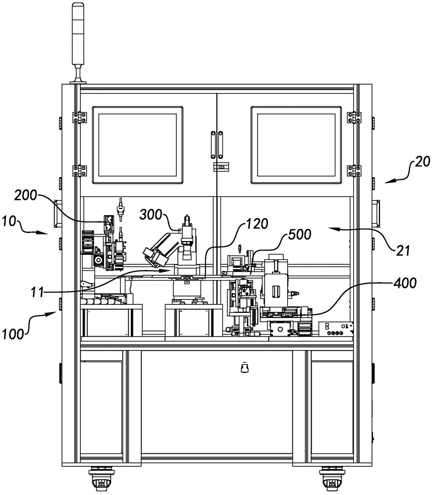
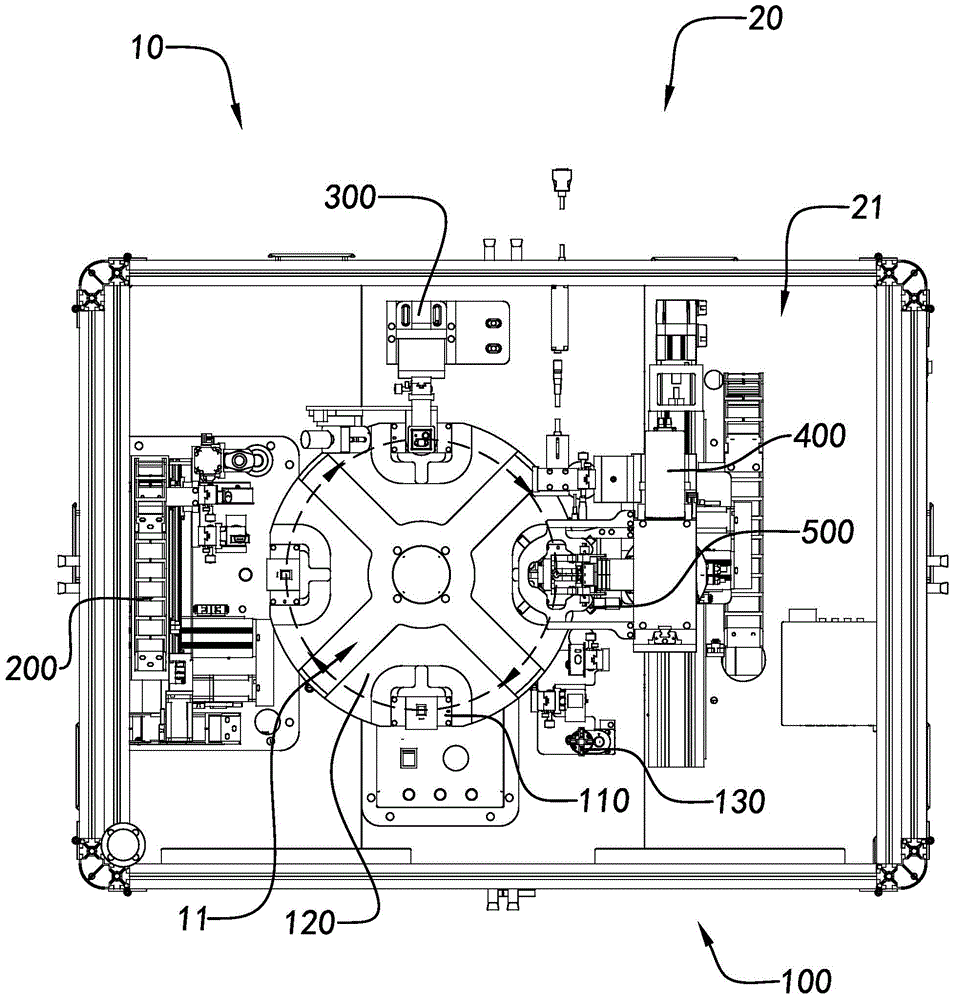
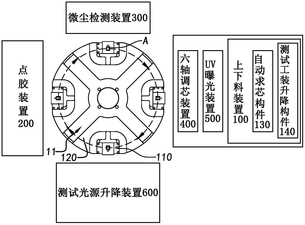
[0069] Such as Figure 1 to Figure 4 Shown is a centering device for an image module A, which includes a plurality of operable devices 10 selectively acting on the image module A to rotate the image module A from one device to another A kind of device, to implement different operation applications on it, realize the online integrated alignment process of the image module A, greatly improve the alignment accuracy and the alignment efficiency of the product, which is conducive to the development of alignment in the automatic mode, reducing The positional accuracy deviation of the image module A in the centering process.

[0070] The centering equipment of the image module A further includes an equipment frame part 20, and the equipment frame part 20 is used for respectively connecting the ...


PUM


Abstract

An aligning apparatus for an image module comprises a plurality of operable devices which are selectively act on an image module so that the image module can rotate from one device to another device and different operation applications can be implemented to achieve the online integrated aligning process of the image module. The operable devices include a loading and unloading device for adjustably mounting the image module; a dispensing device for automatic dispensing operation for the image module; a dust detection device for pre-examining the dust in the image module in a dark field; and a six-axis aligning device for adjusting the relative position of a lens assembly of the image module and a sensor and ensuring the concentricity of the lens optical axis and the vertical axis of the sensor surface. The aligning apparatus for the image module also comprises an apparatus frame member for respective connection of the plurality of operable devices so that the whole machine can be fixed and movable.

Description

technical field [0001] The invention relates to a centering device, in particular to a multi-axis centering device suitable for precise centering in the image module manufacturing process and an application method thereof. Background technique [0002] With the continuous increase of labor costs and the continuous decline in the price of electronic products, manufacturing enterprises, especially optoelectronic product enterprises, are facing increasing pressure on labor costs. If modern enterprises still rely on the low-end production mode of manual work, Undoubtedly, it will face the elimination of the market, and there will be less and less competitive advantage in the mobile phone module industry, no matter in terms of price or quality of mobile phone modules. [0003] The wide use of optical devices has led to the development of optical products towards miniaturization, light weight and high precision, and the quality of optical devices is becoming more and more strictly...

Claims


Application Information

Patent Timeline
Patent Type & Authority Applications(China)
IPC IPC(8): H04N17/00
Inventor 严春琦柯海挺陈成权诸庆梅其敏张宝忠丁亮
Owner NINGBO SUNNY OPOTECH CO LTD
Why Eureka
Try Eureka