Fuel injection system for a turbine engine

A technology of turbine engine and fuel system, applied in the direction of combustion chamber, combustion method, combustion equipment, etc., can solve the problems of low flame temperature, harmfulness, limiting CO emission, etc.

Inactive Publication Date: 2016-06-29
SIEMENS AG
View PDF3 Cites 3 Cited by
  • Summary
  • Abstract
  • Description
  • Claims
  • Application Information

AI Technical Summary

Problems solved by technology

However, because lean flames have low flame temperatures, lean flames are prone to high CO production
And because excess CO production is detrimental, there is a need to limit CO emissions

Method used


Image

  • Fuel injection system for a turbine engine
  • Fuel injection system for a turbine engine
  • Fuel injection system for a turbine engine

Examples


Embodiment Construction

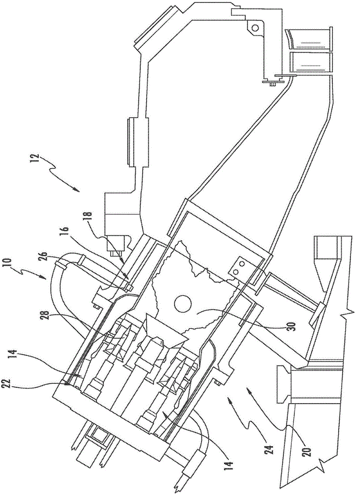
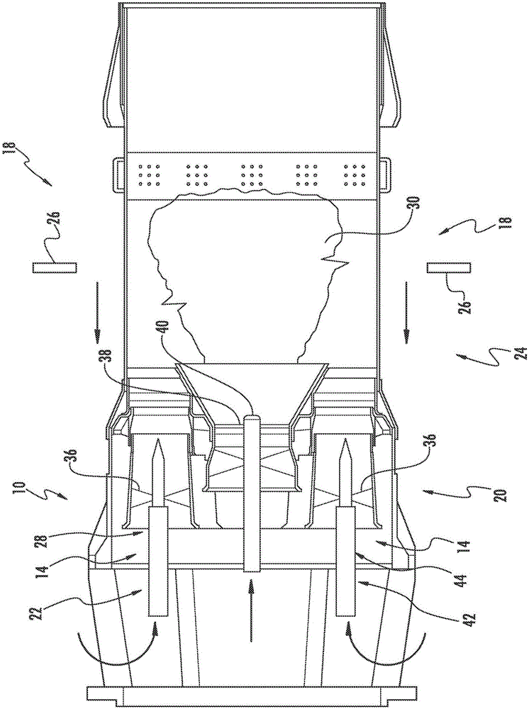
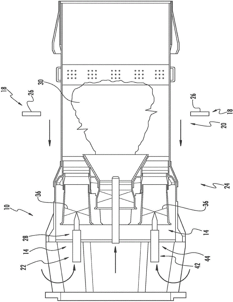
[0020] Such as Figure 1 to Figure 6 As shown, a fuel system 10 for a turbine engine 12 for improving efficiency in a fuel system 10 is disclosed, wherein the primary stage 14 and the secondary stage 16 can maintain acceptable engine power and NOx emissions. Are combined and maintained to a relatively constant fuel ratio. The fuel system 10 may be formed by a first premix injector assembly stage 18 positioned upstream of the flame tube 20, where the first premix injector assembly stage 18 is a secondary injector system. The fuel system 10 may be formed by a first main injector assembly stage 22 as a main injector system positioned downstream of the first premix injector assembly stage 18. The first premix injector assembly stage 18 and the first main injector assembly stage 22 may be coupled together so that the fuel system 10 can simultaneously emit fuel to the fuel system via the first premix injector assembly stage 18 and the main injector assembly stage 22 Inside the combu...


PUM


Abstract

A fuel system (10) for a turbine engine (12) for improving efficiency in a fuel system (10) where a major stage (14) and secondary stage (16) can be combined and held to a relatively constant fuel ratio while maintaining acceptable engine dynamics and NOx emissions is disclosed. The fuel system (10) may be formed from a first premix injector assembly stage (18) positioned upstream from a combustor basket (20), whereby the first premix injector assembly stage (18) is a secondary injector system. The fuel system (10) may be formed from a first primary injector assembly stage (22), which is a main injector system, positioned downstream from the first premix injector assembly stage (18). The first premix injector assembly stage (18) and the first primary injector assembly stage (22) may be coupled together such that the fuel system (10) is capable of emitting fuel into a combustor (24) of the turbine engine (12) via the first premix injector assembly stage (18) and the first primary injector assembly stage (22) simultaneously.

Description

Technical field [0001] The present invention is generally directed to turbine engines, and more particularly relates to fuel systems for turbine engines. Background technique [0002] Typically, a gas turbine engine includes multiple injectors for injecting fuel into a combustor upstream of the flame zone to mix with air. The fuel injectors of conventional turbine engines can be arranged in one of at least three different schemes. The fuel injector can be positioned in a lean-burn premixed flame system in which fuel is injected into the air stream far enough upstream of the location where the fuel / air mixture is ignited so that the air and fuel are in the flame zone It is completely mixed when burning. The fuel injector can also be arranged in a diffusion flame system so that fuel and air are mixed and burned simultaneously. In another configuration, often referred to as a partial premixing system, the fuel injector can inject fuel a sufficient distance upstream of the flame z...

Claims


Application Information

Patent Timeline
Patent Type & Authority Applications(China)
IPC IPC(8): F23R3/28F23R3/34
CPCF23R3/346F23R3/286
Inventor K·C·米杜图里S·P·沃西夫
Owner SIEMENS AG
Why Eureka
Try Eureka