
Pressure sore prevention mattress

A mattress and decubitus technology, which is applied in the field of anti-decubitus mattresses, can solve the problems of heavy workload, increased pain, and low utilization rate, and achieve the effects of preventing decubitus, promoting blood circulation, and facilitating roll storage and handling

Inactive Publication Date: 2016-07-06
傅书赞
View PDF7 Cites 5 Cited by
  • Summary
  • Abstract
  • Description
  • Claims
  • Application Information

AI Technical Summary

Problems solved by technology

[0002] Some patients who need to rest in bed for a long time, because they cannot move and turn over by themselves, the local tissues of the body are under pressure for a long time, and the blood flow is blocked. Nurses need to turn over and massage the patient frequently, and the workload is very heavy. Some orthopedic patients will also experience increased pain due to the movement of their limbs. In view of the above problems, in order to prevent the occurrence of bedsores in long-term bedridden patients, the conventional practice is to use Air bed, but in actual use, due to the high purchase price of the air bed, the use process consumes electric energy, the continuous cost is high, the volume is large, and the effect is still not ideal, which makes it difficult for the air bed to be widely used in clinical practice, and the utilization rate is extremely low

Method used


Image

  • Pressure sore prevention mattress
  • Pressure sore prevention mattress

Examples


Embodiment Construction

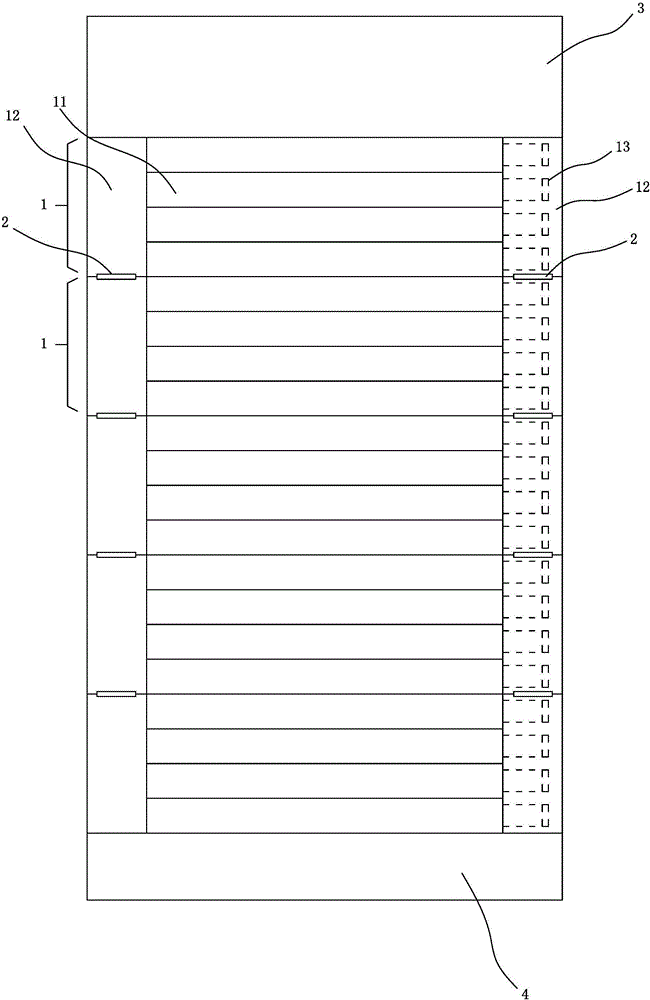
[0020] refer to figure 1 and figure 2 As shown, an anti-decubitus mattress includes a plurality of successively hinged mattress units 1, a headrest 3 hinged on the upper side of the uppermost mattress unit 1, and a footrest hinged on the lower side of the lowermost mattress unit 1 Part 4 and the control device.

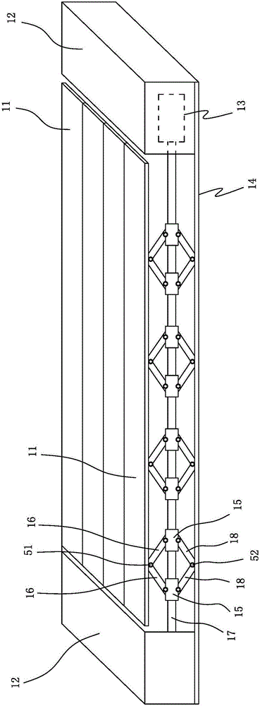
[0021] The mattress unit 1 includes a base plate 14, a plurality of bed plates 11 that can be lifted and lowered above the base plate 14, and a lifting mechanism connected between each bed plate 11 and the base plate 14. The plurality of bed plates 11 extend horizontally and are arranged vertically to form a rectangular bed surface. The base plate 14 is provided with two side beams 12 located at the left and right sides of the rectangular bed surface, and two adjacent mattress units 1 are hinged at the ends of the measuring beams 12 through hinges 2 .

[0022] The lifting mechanism includes a plurality of lifting assemblies arranged along the length direction of th...


PUM


Abstract

A pressure sore prevention mattress comprises one or more mattress units hinged in sequence and control devices; each mattress unit comprises a bottom plate, a plurality of bed boards and lifting mechanisms, wherein the bed boards are arranged above the bottom plate in a lifting manner, and each lifting mechanism is connected between the corresponding bed board and the bottom plate; the control devices are separately connected with the lifting mechanisms of the mattress units and are used for controlling all the lifting mechanisms to act alternately; the bed boards transversely extend and are longitudinally arranged to form a rectangular bed surface; each lifting mechanism comprises a plurality of lifting components, a screw rod and a motor, wherein the lifting components are connected between the corresponding bed board and the bottom plate and are arranged along the length direction of the bed board, each screw rod is transversely arranged on the corresponding lifting components horizontally, and each motor is used for driving the corresponding screw rod to rotate; each lifting component comprises two nuts, two upper link plates and two lower link plates, wherein the two nuts of each lifting component are arranged on the corresponding screw rod at intervals and are opposite in thread, the two upper link plates of each lifting component are hinged between the two corresponding nuts and the corresponding bed board, and the two lower link plates of each lifting component are hinged between the two corresponding nuts and the bottom plate; through forward and reverse rotation of each screw, the two corresponding nuts are driven to move oppositely, so that the upper link plates and the lower link plates are matched to prop up or lower the bed boards.

Description

technical field [0001] The invention relates to an anti-decubitus mattress. Background technique [0002] Some patients who need to rest in bed for a long time, because they cannot move and turn over by themselves, the local tissues of the body are under pressure for a long time, and the blood flow is blocked. Nurses need to turn over and massage the patient frequently, and the workload is very heavy. Some orthopedic patients will also experience increased pain due to the movement of their limbs. In view of the above problems, in order to prevent the occurrence of bedsores in long-term bedridden patients, the conventional practice is to use Air bed, but in actual use, because the purchase price of the air bed is expensive, the use process consumes electric energy, the continuous cost is high, the volume is large, and the effect is still not ideal, which makes the air bed difficult to be widely used in clinical practice, and the utilization rate is extremely low. Contents o...

Claims


Application Information

Patent Timeline
IPC IPC(8): A61G7/057A61G7/07A61G7/075
CPCA61G7/0573A61G7/072A61G7/0755
Inventor 傅书赞
Owner 傅书赞
Learn More