Experimental iron support

An iron platform and experimental technology, which is applied in the field of experimental equipment, can solve the problems of inconvenient movement, insufficient design, and process influence of the central iron rod, and achieve the effects of reducing the risk of the experiment, improving the reliability of the experiment, and preventing accidental slipping

Inactive Publication Date: 2016-07-06
SICHUAN AGRI UNIV
View PDF7 Cites 4 Cited by
  • Summary
  • Abstract
  • Description
  • Claims
  • Application Information

AI Technical Summary

Problems solved by technology

[0003] 1. When the experiment needs to titrate while heating, there will be problems caused by insufficient design. For example, when an electric furnace is added under the experimental instrument for heating, the area of ​​the iron plate below is too small, and the middle iron rod moves Inconvenient, the electric furnace will be placed unstable. At this time, a certain thick material needs to be stacked around the iron plate to avoid this problem, which will make our titration process a safety hazard.
[0004] 2. In the experiment, there are often inconsistent specifications of the instruments. When some instruments are used together, due to the reason that the position does not correspond, it is necessary to adjust the middle iron rod. After the adjustment, because there are only two fixed iron rods on the iron plate Small holes, there will be obstacles in use, which still have a great impact on the experimental process
[0005] 3. The condensing tube clamp matched with the iron stand is a method of post-adjustment of the screw tightness. Although the condensing tube can be fixed more stably before the water is introduced, and the apparent clamping effect is better, it will be due to condensation after the water is introduced. Tube gravity increases and produces a sliding phenomenon, which is easy to cause damage together

Method used


Image

  • Experimental iron support
  • Experimental iron support

Examples


Embodiment Construction

[0021] In order to make the object, technical solution and advantages of the present invention clearer, the present invention will be further described in detail below in conjunction with the accompanying drawings and embodiments. It should be understood that the specific embodiments described here are only used to explain the present invention, not to limit the present invention.

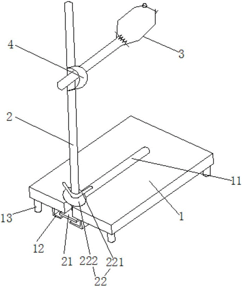
[0022] Such as figure 1 with figure 2 The shown iron frame platform for experiment includes base plate 1, iron rod 2 and condenser pipe clamp 3, and the middle part of the base plate 1 is provided with a notch groove whose length is 3 / 4 of the total length along its length direction. 11. An L-shaped baffle 12 is arranged symmetrically to both sides of the notch 11 at the bottom of the notch 11, and a square iron sheet 21 built into the L-shaped baffle 12 is welded and fixed at the bottom of the iron rod 2, and the The iron rod 2 can move back and forth along the notch groove 11, and the iron rod...


PUM


Abstract

The invention discloses an experimental iron support, which comprises a base plate, an iron rod and a condenser pipe clamp, wherein an undercut groove of which the length is 3 / 4 of total length is formed in the middle part of the base plate along the length direction; an opening is formed in the end part of the undercut groove; L-shaped baffle plates are arranged at two sides, symmetrical with the undercut groove, at the bottom part of the undercut groove; a square iron sheet which is internally arranged on the L-shaped baffle plates is fixed and welded to the bottom part of the iron rod; the iron rod can move forwards and backwards along the undercut groove; a locking cap which is used for being withheld at the upper part of the undercut groove is screwed on the iron rod; a shaft lever of the condenser pipe clamp is vertically fixed to the iron rod through a bench clamp arranged on the iron rod; two symmetrically arranged arc-shaped clamping jaws are hinged with the front end of the shaft lever; and a front-end locking device is arranged at the front end of each arc-shaped clamping jaw. According to the experimental iron support, free adjustment on the position of the iron rod can be achieved; meanwhile, the clamping stability of the condenser pipe clamp is improved; and the reliability is improved.

Description

technical field [0001] The invention relates to the technical field of experimental equipment, in particular to an iron stand for experiments. Background technique [0002] The existing iron stand in the laboratory is generally composed of a cylindrical iron rod with a height of 0.5m and a rectangular iron plate base with an area of ​​about 180cm2. There are small holes at the geometric center and 1 / 3 geometric center of the bottom for adjustment. The position of the iron rod is to realize the proper placement of the experimental utensils. When in use, it is generally equipped with cross clamps, butterfly clamps, universal test tube clamps and iron rings to fix and support various experimental instruments. This type of iron stand is widely used in conjunction with distillation, heating, filtration and other operational instruments in the laboratory, and is an indispensable type of experimental instrument for various chemical and biological laboratories. There are following ...

Claims


Application Information

Patent Timeline
Patent Type & Authority Applications(China)
IPC IPC(8): B01L9/00
CPCB01L9/00
Inventor 林德荣秦涛纪冉王瑞琦刘鹏王丹邹锦鹏吴任之张清吴贺君刘耀文叶劲松苏赵
Owner SICHUAN AGRI UNIV
Why Eureka
Try Eureka