Drum structure of hydraulic pipe cleaning machine

A technology for hydraulic pipes and washing machines, which is applied in the directions of cleaning methods using liquids, cleaning hollow objects, cleaning methods and utensils, etc., can solve the problems of poor cleaning efficiency and high cost, and achieves reduction of cleaning costs, improvement of cleanliness levels, and shortening of Effect of cleaning time

Active Publication Date: 2018-05-04
HTH CLEANING TECH SUZHOU LTD
View PDF6 Cites 0 Cited by
  • Summary
  • Abstract
  • Description
  • Claims
  • Application Information

AI Technical Summary

Problems solved by technology

[0005] The invention provides a drum structure of a hydraulic pipe cleaning machine, the purpose of which is to solve the problems of poor cleaning efficiency and high cost in the prior art

Method used


Image

  • Drum structure of hydraulic pipe cleaning machine
  • Drum structure of hydraulic pipe cleaning machine
  • Drum structure of hydraulic pipe cleaning machine

Examples


Embodiment

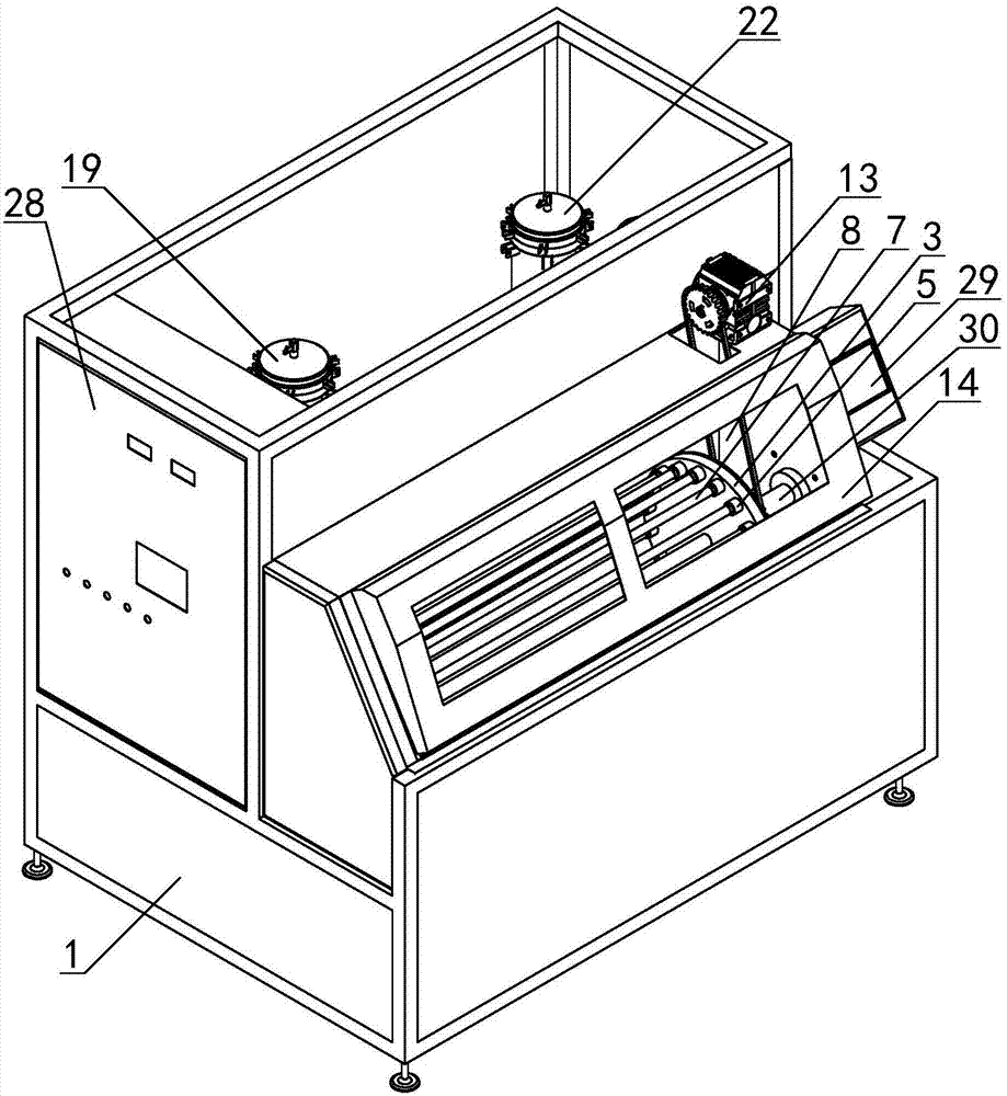
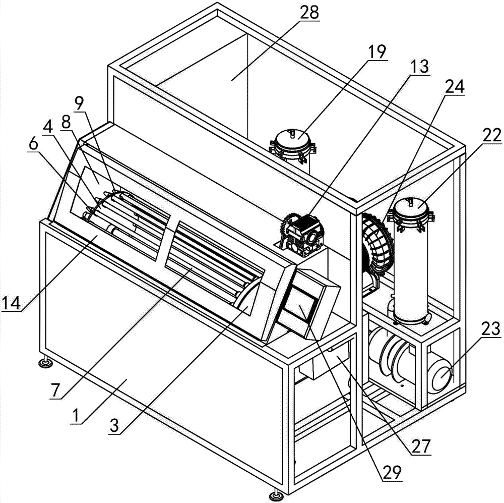
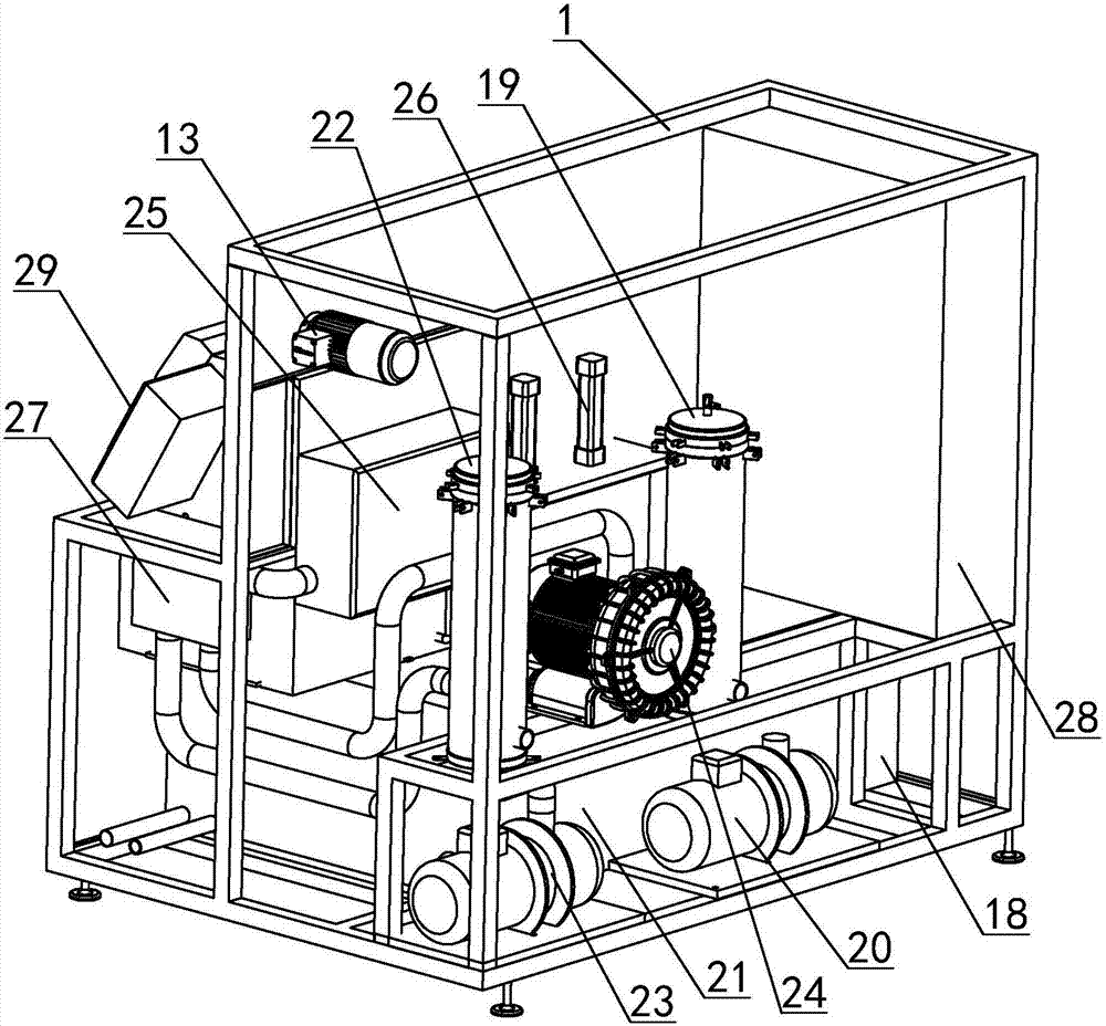
[0038] Example: see attached Figure 1~4 As shown, a drum structure of a hydraulic pipe cleaning machine, the cleaning machine includes a frame 1, and a drum structure connected to the frame 1, a cleaning unit, a rinsing unit and a drying unit. (In order to show the structural structure, the rack in the figure hides the side panel, top panel and back panel)

[0039] Such as Figure 5~14 As shown, the drum structure includes a drum and a water tank 2; the drum includes a first chucking disc 3, a second chucking disc 4 and a rotating shaft 31; the first chucking disc 3 and the second chucking disc The chucking discs 4 are arranged in parallel, and are all interspersed with the rotating shaft 31 by their hubs; on the surface of the first chucking disc 3 opposite to the second chucking disc 4, a plurality of hydraulic pipes are arranged. A positioning part 5, the first positioning part 5 of each hydraulic pipe is evenly distributed along the circumferential direction of the cent...


PUM


Abstract

The invention relates to a drum structure of a hydraulic pipe cleaning machine. The drum structure is characterized by comprising a drum and a water trough, wherein the drum is rotatably connected to the interior of a cavity of a rack, and the water trough is arranged at the bottom of the cavity; the drum comprises a first clamping disk, a second clamping disk and a rotating shaft; a plurality of hydraulic pipe first positioning parts are arranged on the first clamping disk, and a plurality of hydraulic pipe second positioning parts are correspondingly arranged on the second clamping disk; all of the hydraulic pipe first positioning parts are communicated with a gas-liquid pipeline in the cavity, all of the hydraulic pipe second positioning parts are respectively communicated with nozzles, and all of the nozzles are fixedly arranged on one side, which faces outwards, of the second clamping disk; the drum is horizontally arranged in the cavity, and at least one hydraulic pipe in the drum is positioned in the water trough; an ultrasonic vibrating plate is arranged in the water trough. The drum structure has the advantage of smart design, a plurality of hydraulic pipes can be simultaneously clamped, the hydraulic pipes can be conveniently installed and removed, by adopting the design of rotation for 360 degrees, the cleaning time can be shortened, the cleanliness grade can be increased, the cleaning cost can be reduced, and the cleaning efficiency can be improved.

Description

technical field [0001] The invention relates to an automatic cleaning device, in particular to a drum structure of a fully automatic hydraulic pipe cleaning machine, which includes cleaning, rinsing and drying functions. Background technique [0002] Hydraulic pipe is a widely used component in construction machinery. It can be divided into plastic pipe and metal pipe according to the material. Among them, after the hydraulic pipe made of metal is extruded, it needs to be cut off and coated with anti-rust oil for preservation. The hydraulic pipe needs to be cleaned before assembly and use to remove impurities such as particles remaining inside and outside the pipe when it is cut off, and to clean the anti-rust oil attached to the pipe body. [0003] At present, when cleaning hydraulic pipes, methods such as scrubbing the surface with metal brushes, blowing the inner wall with compressed air, soaking with oil or chemical solvents, blowing with sponges, and high-pressure wate...

Claims


Application Information

Patent Timeline
Patent Type & Authority Patents(China)
IPC IPC(8): B08B9/02B08B9/023B08B9/032B08B3/12B08B13/00
CPCB08B3/12B08B9/02B08B9/023B08B9/0321B08B13/00
Inventor 王利刚侯栋
Owner HTH CLEANING TECH SUZHOU LTD
Why Eureka
Try Eureka