
Multifunctional snow removing rescue vehicle

A rescue vehicle, multi-functional technology, applied in the field of multi-functional snow removal and rescue vehicles, can solve problems such as road damage, road surface corrosion, environmental pollution, etc., and achieve the effect of easy deployment and great practicability

Inactive Publication Date: 2016-07-06
LONGYAN HAIDEXIN AUTOMOBILE
View PDF8 Cites 2 Cited by
  • Summary
  • Abstract
  • Description
  • Claims
  • Application Information

AI Technical Summary

Problems solved by technology

Among all kinds of driving safety hazards, road snow and icing caused by extreme winter weather are the most serious. When major traffic accidents are caused by road snow or icing, rescue vehicles often have to wait for the road to be cleared of snow or icing The scene of the accident could not be reached until later, which delayed the golden time for rescue.
[0003] Existing snow removal vehicles only have a single snow removal function, and often when the accident scene requires accident vehicle towing service or emergency power supply, the existing snow removal vehicles are not competent. At the same time, most of the existing snow removal vehicles are mainly mechanical snow removal and salt spreading , the former is not thorough enough to remove snow, and the ice breaker may also cause damage to the road; the latter will pollute the environment, and a large amount of snow-melting salt will cause corrosion to the road surface at the same time, increasing the cost of later maintenance and use. A functional snow removal and rescue vehicle can ensure rapid snow removal and ice breaking without damaging the road, and it is also required to have certain rescue capabilities

Method used


Image

  • Multifunctional snow removing rescue vehicle
  • Multifunctional snow removing rescue vehicle
  • Multifunctional snow removing rescue vehicle

Examples


Embodiment Construction

[0020] The present invention will be further described below in conjunction with the description of the drawings and specific embodiments.

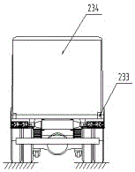
[0021] Such as figure 1 , figure 2 , image 3 and Figure 4 As shown, a multifunctional snow removal and rescue vehicle includes a chassis vehicle 1 and a compartment 2. A generator set 221, a power distribution cabinet 16, a snow blower 212 and a boom device 231 are arranged in the compartment 2. The boom device 231 includes a controller 232 , the connecting rod 233 and the flip door 234; the snow blower 212, the controller 232 and the electric connecting rod 233 are respectively connected to the power distribution cabinet 16 through cables. The controller 232 can control the operation of the boom device 231 . The power distribution cabinet 16 can control the start and stop of the generator set 221, the instrument can display various parameters of the power supply, and the power distribution switch can control the load on and off po...


PUM


Abstract

The invention relates to a rescue device, in particular to a multifunctional snow removing rescue vehicle. The multifunctional snow removing rescue vehicle comprises a chassis vehicle body and a carriage. A power generating unit, a power distributing cabinet, snow removers and a suspension arm device are arranged in the carriage. The suspension arm device comprises a controller, a connecting rod and a turnover door. The snow removers, the controller and the connecting rod are connected with the power distributing cabinet through cables correspondingly. Compared with the prior art, the snow removing equipment, the rescue equipment and the power supply guaranteeing equipment are simultaneously arranged in the carriage, so that the multifunctional snow removing rescue vehicle has the characteristics of being flexible, easy to deploy and the like; traditional snow removing is replaced by jetting type snow removing, and ice and snow on road surfaces are thawed through high-speed gas flow jetted by the jetting type snow removers; and meanwhile, the jetting type snow removing rescue vehicle has the functions of snow removing, vehicle rescue, emergency power energy outputting and the like through rescue suspension arms and the power generating unit, meets the multi-functionalization requirement of markets and has huge practicability.

Description

technical field [0001] The invention relates to a rescue device, in particular to a multifunctional snow removal and rescue vehicle. Background technique [0002] With the continuous improvement of infrastructure in the country, the construction of a large number of expressways and viaducts has greatly increased the traffic speed. At the same time, it has also put forward higher requirements for the emergency rescue system when traffic accidents occur. Among all kinds of driving safety hazards, road snow and icing caused by extreme winter weather are the most serious. When major traffic accidents are caused by road snow or icing, rescue vehicles often have to wait for the road to be cleared of snow or icing Only after arriving at the accident scene, the golden time for rescue was delayed. [0003] Existing snow removal vehicles only have a single snow removal function, and often when the accident scene requires accident vehicle towing service or emergency power supply, the ...

Claims


Application Information

Patent Timeline
Patent Type & Authority Applications(China)
IPC IPC(8): B60P3/00B60P1/54E01H5/10
CPCB60P3/00B60P1/5428E01H5/106
Inventor 林卡李钦龙
Owner LONGYAN HAIDEXIN AUTOMOBILE
Learn More