
Automatic sorting and conveying device

A technology of conveying device and conveying rack, which is applied in the direction of conveyor objects, transportation and packaging, etc., can solve the problems of complex structure, loud noise, different lengths and specifications of rods, etc., and achieves compact structure, wide adaptability and good feasibility. Effect

Active Publication Date: 2016-07-06
ZHEJIANG UNIV +3
View PDF22 Cites 10 Cited by
  • Summary
  • Abstract
  • Description
  • Claims
  • Application Information

AI Technical Summary

Problems solved by technology

[0002] Slender round or square rod materials occupy a large proportion in social production. In industrial production, at present, small particle parts (such as screws, nuts, rectangular blocks, cylindrical particles, etc.) are automatically arranged into regular arrangements, and then conveyed To the next feeding port can be achieved by a vibrating feeder, but if the slender circular or square rod materials need to be arranged neatly, especially if they are neatly arranged and transported to the next feeding port one by one, due to the rod itself Flexibility, there is still no good solution so far. It is inconvenient to use the vibration feeding method. On the one hand, it is difficult to ensure the surface quality of the rods. On the other hand, due to the different length specifications of the rods, it is difficult to design a Vibration feeding device for parts, and due to the relatively complex structure, severe vibration will generate large noise, which will affect the environment and workers' health
[0003] So far, there is no automatic sorting and conveying device with good feasibility, high automation and wide adaptability for slender round or square rod materials on the market

Method used


Image

  • Automatic sorting and conveying device
  • Automatic sorting and conveying device
  • Automatic sorting and conveying device

Examples


Embodiment

[0032] As an embodiment of the present invention, the single-chip microcomputer can adopt the MCS-51 series of INTEL Company, such as 89C52; the first motor 21 and the second motor 13 can adopt existing servo motors on the market, such as the Baofuli motor 6UG-20K Model; the counting sensor can adopt the infrared sensor of HD-DS30CM type; the above-mentioned devices can be used in the automatic sorting and conveying device in the present invention, but are not limited to the above-mentioned models.

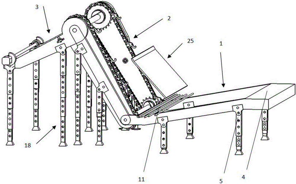
[0033] In the factory, during the automatic sorting and feeding process of the slender circular rod materials 11, when starting to work, a bundle of materials 11 is placed on the feeding rack 4 of the feeding unit 1, and the feeding rack 4 is close to the baffle plate 34 One side is lower than the other side, and the material 11 slides against the baffle plate 34 on the lower side of the upper material rack 4. At this time, the material 11 is aligned along the baffle plate 34, and ...


PUM


Abstract

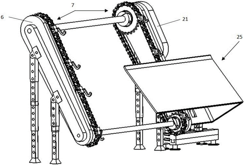
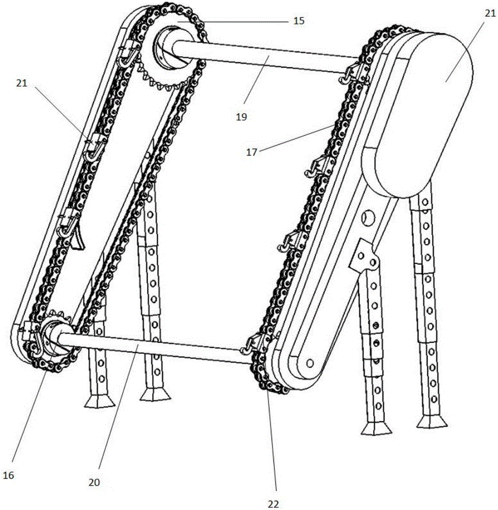
The invention discloses an automatic sorting and conveying device which is used for sorting and conveying materials. The automatic sorting and conveying device comprises a feeding unit, a sorting and conveying unit, a discharging unit, a supporting unit and a single-chip microcomputer, wherein the feeding unit, the sorting and conveying unit and the discharging unit are sequentially hinged and supported by the supporting unit; the sorting and conveying unit sorts and conveys materials arranged on a feeding frame one by one; the discharging unit sorts out and discharges the materials conveyed by the sorting and conveying unit to a next feeding port one by one; the sorting and conveying unit and the discharging unit are both connected with the single-chip microcomputer; the single-chip microcomputer is used for controlling the speed of sorting, conveying and discharging. The structural characteristics that rods are thin, long and bent are effectively overcome through a method of two times of hooking, the production method for sorting and feeding of thin and long round or square rod materials is totally changed, and the automatic sorting and conveying device is good in feasibility, high in intelligence and high in applicability.

Description

technical field [0001] The invention relates to a conveying device, in particular to an automatic sorting conveying device. Background technique [0002] Slender round or square rod materials occupy a large proportion in social production. In industrial production, at present, small particle parts (such as screws, nuts, rectangular blocks, cylindrical particles, etc.) are automatically arranged into regular arrangements, and then conveyed To the next feeding port can be achieved by a vibrating feeder, but if the slender circular or square rod materials need to be arranged neatly, especially if they are neatly arranged and transported to the next feeding port one by one, due to the rod itself Flexibility, there is still no good solution so far. It is inconvenient to use the vibration feeding method. On the one hand, it is difficult to ensure the surface quality of the rods. On the other hand, due to the different length specifications of the rods, it is difficult to design a ...

Claims


Application Information

Patent Timeline
Patent Type & Authority Applications(China)
IPC IPC(8): B65G47/14
CPCB65G47/1478
Inventor 王杭州陈瑶宋宏方美芬杨萍曹权
Owner ZHEJIANG UNIV
Learn More