Infrared heating ironing roller combustion device

A combustion device, ironing roller technology, applied in the direction of burner, combustion method, combustion type, etc., can solve the problems of high energy consumption, high energy consumption of electric heating ironing roller, no oil boiler heating system, etc., to achieve faster Heating process, good energy-saving effect, and the effect of saving high-power electricity

Inactive Publication Date: 2016-07-06
LIANYUNGANG CITY RUNIAN MACHINE
View PDF5 Cites 2 Cited by
  • Summary
  • Abstract
  • Description
  • Claims
  • Application Information

AI Technical Summary

Problems solved by technology

At present, the electric heating roller uses 24 electric heating tubes, and the power consumption is about 56KW. The energy consumption is high and the production cost is high, which directly affects the economic benefits of the production enterprise.
To solve the problem of high energy consumption of electric heating ironing rollers, oil ironing rollers have been developed, which effectively reduces energy consumption; however, most small and medium-sized enterprises are restricted by environmental protection policies and other factors, and cannot use oil boiler heating systems. Oil heating ironing roller ironing machine

Method used


Image

  • Infrared heating ironing roller combustion device

Examples


Embodiment 1

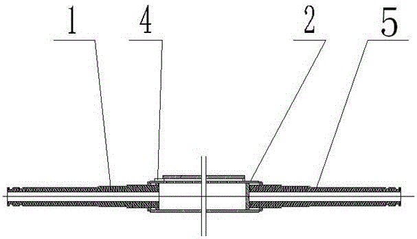
[0017] Such as figure 1 As shown, an infrared heating ironing roller combustion device includes a left shaft head 1, a gas pipe 2, an igniter 4 and a right shaft head 5; one end of the left shaft head 1 is connected to a gas pipe, and the left shaft head 1 The other end of the gas pipe 2 is connected to one end of the gas pipe 2, the other end of the gas pipe 2 is connected to one end of the right shaft head 5, and the other end of the right shaft head 5 is sealed; the gas pipe 2 is axially provided with a set of gas holes, the surface of the gas pipe 2 is coated with a high emissivity infrared coating; each group of gas holes includes three rows of gas holes uniformly distributed, and the radial angle range of each group of gas holes is 10 ° ~ 30 °, the diameter of the gas holes It is 3mm; it is located at the junction of the left shaft head 1 and the gas pipe 2, and the gas pipe 2 is provided with an igniter 4; wherein, the gas pipe 2 is made of ceramics.

Embodiment 2

[0019] Such as figure 1 As shown, an infrared heating ironing roller combustion device includes a left shaft head 1, a gas pipe 2, an igniter 4 and a right shaft head 5; one end of the left shaft head 1 is connected to a gas pipe, and the left shaft head 1 The other end of the gas pipe 2 is connected to one end of the gas pipe 2, the other end of the gas pipe 2 is connected to one end of the right shaft head 5, and the other end of the right shaft head 5 is sealed; the gas pipe 2 is axially provided with two sets of Gas holes, the surface of the gas pipe 2 is coated with a high-emissivity infrared coating; each group of gas holes includes three rows of gas holes uniformly distributed, and the radial angle range of each group of gas holes is 10 ° ~ 30 °. The diameter is 2 mm; it is located at the junction of the left shaft head 1 and the gas pipe 2, and the gas pipe 2 is provided with an igniter 4; wherein, the gas pipe 2 is made of ceramics.

Embodiment 3

[0021] Such as figure 1 As shown, an infrared heating ironing roller combustion device includes a left shaft head 1, a gas pipe 2, an igniter 4 and a right shaft head 5; one end of the left shaft head 1 is connected to a gas pipe, and the left shaft head 1 The other end of the gas pipe 2 is connected to one end of the gas pipe 2, the other end of the gas pipe 2 is connected to one end of the right shaft head 5, and the other end of the right shaft head 5 is sealed; the gas pipe 2 is axially provided with three groups of gas holes, the surface of the gas pipe 2 is coated with a high emissivity infrared coating; each group of gas holes includes three rows of gas holes uniformly distributed, and the radial angle range of each group of gas holes is 10 ° ~ 30 °, the diameter of the gas holes It is 1 mm; it is located at the connection between the left shaft head 1 and the gas pipe 2, and the gas pipe 2 is provided with an igniter 4; wherein, the gas pipe 2 is made of ceramics.

[...


PUM


Abstract

The invention discloses an infrared heating ironing roller combustion device. The infrared heating ironing roller combustion device comprises a left shaft head, a fuel gas pipe, an igniter and a right shaft head, wherein one end of the left shaft head is connected with a gas conveying pipe and the other end of the left shaft head is connected with one end of the fuel gas pipe; the other end of the fuel gas pipe is connected with one end of the right shaft head and the other end of the right shaft head is sealed; a plurality of fuel gas holes are formed in the fuel gas pipe; the surface of the fuel gas pipe is coated with a high-reflection-rate infrared coating; the igniter is arranged on the fuel gas pipe at the joint of the left shaft head and the fuel gas pipe. The infrared heating ironing roller combustion device provided by the invention adopts a natural gas combustion heating manner so that large-power power utilization is saved; the infrared heating ironing roller combustion device adopts an infrared conduction technology so that the energy-saving effect is good and the energy-saving efficiency is not less than 35%.

Description

technical field [0001] The invention relates to the technical field of textile post-finishing mechanical ironing machines, in particular to an infrared heating ironing roller combustion device. Background technique [0002] The ironing roller is a core part of the plush fabric ironing machine, and its function is to straighten the wool surface fibers of the plush fabric and make it elastic and glossy. The heating method of the traditional ironing roller is electric heating, and the roller body reaches the working temperature through heating by the electric heating tube inside the roller body. At present, the electric heating roller uses 24 electric heating tubes, and the power consumption is about 56KW. The energy consumption is high and the production cost is high, which directly affects the economic benefits of the production enterprise. To solve the problem of high energy consumption of electric heating ironing rollers, oil ironing rollers have been developed, which effe...

Claims


Application Information

Patent Timeline
Patent Type & Authority Applications(China)
IPC IPC(8): D06C15/08F23D14/12F23D14/58
CPCD06C15/08F23D14/12F23D14/58
Inventor 张昊张波唐考成
Owner LIANYUNGANG CITY RUNIAN MACHINE
Why Eureka
Try Eureka