High-speed railway rush repair beam capable of being converted into permanent bridge structure, and rush repair method of high-speed railway rush repair beam

A bridge structure, high-speed railway technology, applied in bridges, buildings, etc., can solve the problems of slow traffic speed, no emergency repair equipment reserves, no emergency repair technical support, etc., to improve vertical stiffness and lateral stiffness, increase temporary traffic speed, The effect of improving the speed of on-site fights

Active Publication Date: 2016-07-06
SHIJIAZHUANG TIEDAO UNIV
View PDF6 Cites 8 Cited by
  • Summary
  • Abstract
  • Description
  • Claims
  • Application Information

AI Technical Summary

Problems solved by technology

At present, there is no special equipment reserve for high-speed railway bridge repair at home and abroad. The existing beam repair equipment is developed for ordinary railway bridge repair, including 64-type railway military beams, 87-type railway emergency repair steel beams and disassembled beams, etc. However, these beam repair equipments have the disadvantages of slow t...

Method used


Image

  • High-speed railway rush repair beam capable of being converted into permanent bridge structure, and rush repair method of high-speed railway rush repair beam
  • High-speed railway rush repair beam capable of being converted into permanent bridge structure, and rush repair method of high-speed railway rush repair beam
  • High-speed railway rush repair beam capable of being converted into permanent bridge structure, and rush repair method of high-speed railway rush repair beam

Examples


Embodiment Construction

[0050] In order to make the purpose, technical solution and advantages of the present invention clearer, the invention will be clearly and completely described below in conjunction with the accompanying drawings and specific embodiments.

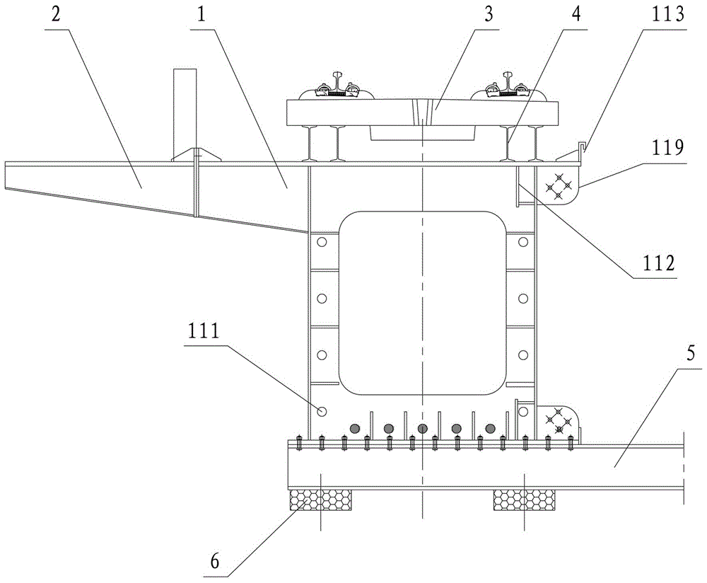
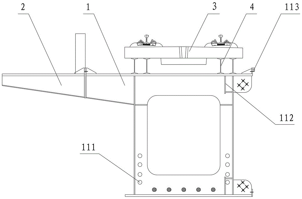
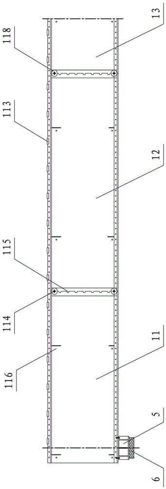
[0051] like Figure 1-10 A high-speed railway emergency repair beam that can be converted into a permanent bridge structure is shown, which includes an I-beam 7 connecting the bridge span and a single-wire steel beam that is respectively arranged on the left and right sides of the I-beam 7 and connected with the I-beam 7 Box girder 1, the bridge pier pad stone is provided with a support pad beam 5 through a temporary support 6, the two ends of the I-beam 7 and the single-line steel box girder 1 are located on the support pad beam 5, and the single-line The steel box girder 1 is spliced ​​by a plurality of box girder segments, and the upper end surface of the single-line steel box girder 1 is provided with a ballastless track slab 3 through a...


PUM


Abstract

The invention discloses a high-speed railway rush repair beam capable of being converted into a permanent bridge structure, and a rush repair method of the high-speed railway rush repair beam. The high-speed railway rush repair beam is formed by single-line uplink rush repair beams and single-line downlink rush repair beams which are independent of one another in a temporary traffic state; the single-line rush repair beams respectively adopt a structural form of a prestressed steel box girder, the steel box girders are manufactured in a way of segmentation, and segments of each steel box girder are connected in a manner of steel pin-shear key; a longitudinal external prestressed reinforcing steel bar is arranged above a lower wing plate of each steel box girder and at the inner side of a web of the steel box girder. By means of pouring a concrete structure layer above the steel box girders as well as arranging and tensioning transverse prestressed tendons between the single-line uplink rush repair beams and the single-line downlink rush repair beams, a double-track and whole-span prestressed steel-concrete composite beam is formed by the rush repair beams and can be used as the permanent bridge structure for normal operation. Compared with the existing rush repair steel beam, the high-speed railway rush repair beam is characterized in that the traffic speed is high, a beam part structure used for temporary rush repair is no longer dismantled, and the temporary rush repair beam is converted into the permanent bridge structure by the conversion of a structural system, so that beam-replacing construction of a damaged bridge is further avoided.

Description

technical field [0001] The invention relates to a high-speed railway bridge repair equipment and a repair method thereof, in particular to a high-speed railway medium-span simply supported beam bridge structural repair equipment, which belongs to the technical field of bridge repair. Background technique [0002] In the high-speed railway, the bridge mileage accounts for a high proportion of the total mileage of the line. Although the design and construction standards of high-speed railway bridges are very high, considering their huge number and wide geographical distribution, the potential for disaster damage is relatively high. At present, there is no special equipment reserve for high-speed railway bridge repair at home and abroad. The existing beam repair equipment is developed for ordinary railway bridge repair, including 64-type railway military beams, 87-type railway emergency repair steel beams and disassembled beams, etc. However, these beam repair equipment all ha...

Claims


Application Information

Patent Timeline
IPC IPC(8): E01D2/00E01D15/00
CPCE01D2/00E01D15/00
Inventor 李朝红徐光兴孙志星刘嘉武郭孟娇王钗
Owner SHIJIAZHUANG TIEDAO UNIV
Why Eureka
Try Eureka