
Device for removing highway floating snow through air blowing

A highway, wind blowing technology, applied in snow surface cleaning, construction, cleaning methods, etc., can solve the problems of increasing snow removal cost, lack of snow removal timeliness, affecting driving safety, etc., to ensure snow removal effect, good snow removal effect, The effect of ensuring the stability

Inactive Publication Date: 2016-07-06
JILIN UNIV
View PDF9 Cites 0 Cited by
  • Summary
  • Abstract
  • Description
  • Claims
  • Application Information

AI Technical Summary

Problems solved by technology

However, this snow removal method needs to close the expressway. In addition to increasing the cost of snow removal to a large extent, from the perspective of environmental protection, salt will cause great damage to the road surface of the expressway. The environment produces pollution, which harms the plants on both sides of the road
In addition, this snow removal method has a big disadvantage. Its prerequisite is the need for sunlight. However, for highways in mountainous areas, the high mountains will block the sunlight, resulting in The temperature is low, the effect of snow melting is greatly reduced, and the timeliness of snow removal is not available, that is to say, this snow removal method cannot achieve timely snow removal
To sum up, this method of snow removal by sprinkling salt and removing snow cannot timely and thoroughly clear the snowfall on the expressway, so it will cause the expressway to freeze. Safety is the main cause of traffic accidents in cold winter areas, so it is of great significance to develop a high-efficiency road snow removal device that can be used with common loaders

Method used


Image

  • Device for removing highway floating snow through air blowing
  • Device for removing highway floating snow through air blowing
  • Device for removing highway floating snow through air blowing

Examples


Embodiment Construction

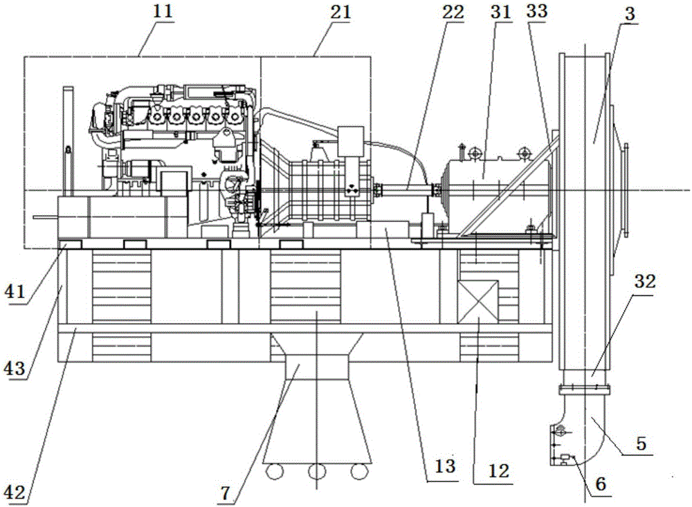
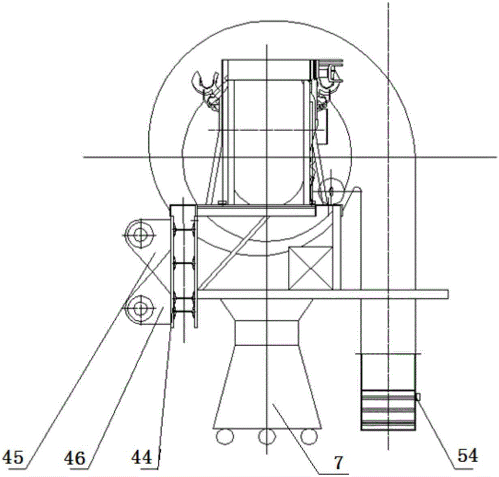
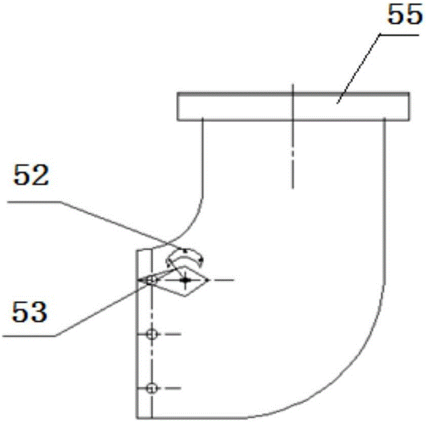
[0026] Such as figure 1 , figure 2 As shown, the power output device of the wind blowing and snow removal device for highways of the present invention includes a power output device, a power transmission device, a fan 3, a support mechanism, a modified air nozzle 5, an air outlet ground clearance adjustment system, and a lifting mechanism .

[0027] Described power output device comprises engine assembly 11, fuel tank 12 and storage battery 13; Fuel tank 12 is connected with engine assembly 11 by pipeline, supplies oil for engine assembly 11; Storage battery 13 is connected with engine assembly 11 by electric wire, is The engine assembly 11 supplies power.

[0028] The power transmission device includes a transmission 21 and a universal joint 22 ; one end of the transmission 21 is coaxially connected with the output shaft of the engine assembly 11 , and the other end is coaxially connected with the bearing housing 31 of the fan 3 through the universal joint 22 . Fan 3 adop...


PUM


Abstract

The invention relates to a device for removing highway floating snow through air blowing. A power output device of the device comprises an engine assembly, an oil tank and a storage battery. An upper supporting bumper bracket and a lower supporting bumper bracket of a supporting mechanism are connected through a plurality of side face supporting bumper brackets. A back plate is fixedly connected with the upper supporting bumper bracket and the lower supporting bumper bracket. An upper pin boss and a lower pin boss are fixed to the back plate. The engine assembly, the storage battery and a ventilator are fixed to the upper supporting bumper bracket. The oil tank is fixed to the lower supporting bumper bracket. A lifting mechanism is arranged under the lower supporting bumper bracket. According to the device, the snow removing power is provided by an independent power output device, the working speed is provided by a driving machine which is matched with the device, and snow removing is conducted through the ventilator; and snow removing is convenient and timely, the efficiency is high, and the road surface is prevented from being damaged. In addition, the device can be matched with a plurality of power machines such as road rollers, loaders, forklifts and traditional snow removers, and the application range is quite wide.

Description

technical field [0001] The invention belongs to the technical field of road snow removal, and in particular relates to a detachable wind blowing snow floating device for highways which is conveniently installed on various driving machines. Background technique [0002] The winter temperature in the cold region of Northeast China is low, and the snow layer on the roads that is not cleared in time after the snowfall will form a hard ice layer after being rolled by vehicles. When this happens, the labor hours required to clear snow from highways can increase significantly. According to statistics, at present, the way of salting and melting snow is the most common way to clear snow on highways. However, this snow removal method needs to close the expressway. In addition to increasing the cost of snow removal to a large extent, from the perspective of environmental protection, salt will cause great damage to the road surface of the expressway. The environment produces pollution...

Claims


Application Information

Patent Timeline
IPC IPC(8): E01H5/10
CPCE01H5/106
Inventor 李世武魏雨浓张景海徐聪黄庆春于欣彤孙宝全周瑞成罗泰然
Owner JILIN UNIV
Learn More