Burner for gas stove and gas stove

A gas stove and burner technology, which is applied in the directions of gas fuel burners, burners, combustion methods, etc., can solve the problems of the complex structure of the fixed bracket, the influence of the ejection effect, and the change of the distance between the ejection tube and the nozzle.

Inactive Publication Date: 2016-07-06
BSH ELECTRICAL APPLIANCES JIANGSU +1
View PDF5 Cites 2 Cited by
  • Summary
  • Abstract
  • Description
  • Claims
  • Application Information

AI Technical Summary

Problems solved by technology

In the prior art, the nozzle and the injection tube are generally fixed on the same fixed bracket to determine the gap d between the two, but loosening easily occurs between the injection tube and the fixed bracket, so that the distance between the injection tube and the nozzle changes, causing instability in the gap d
[0004] There are also some exist

Method used


Image

  • Burner for gas stove and gas stove
  • Burner for gas stove and gas stove
  • Burner for gas stove and gas stove

Examples


Embodiment Construction

[0028] In order to make the above objects, features and advantages of the present invention more comprehensible, specific embodiments of the present invention will be described in detail below in conjunction with the accompanying drawings.

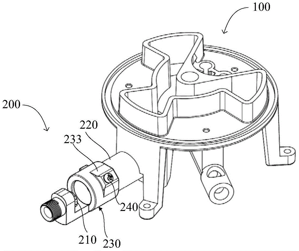
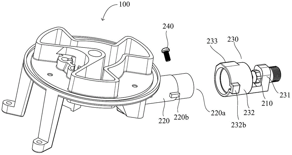
[0029] An embodiment of the present invention provides a burner, referring to Figure 2-5 As shown, it includes a burner base 100 and an injection device 200 connected to the burner base 100 . The injection device 200 mixes gas and air according to a certain ratio and delivers them to the burner base 100 .

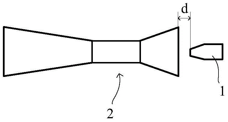
[0030] The injection device 200 includes a nozzle 210 , an injection tube 220 and a fixing bracket 230 , the injection tube 210 is integrally formed on the burner base 100 , and the fixing bracket 230 is used for connecting the nozzle 210 and the injection tube 220 . Wherein, the spout 210a of nozzle 210 ( Figure 4 ) is aligned with the entrance 220a of the injection tube 220 ( image 3 , Figure 4 ), there is a gap between the noz...


PUM


Abstract

A burner for a gas stove and a gas stove, wherein the burner includes a nozzle and an injection pipe, the nozzle of the nozzle is aligned with the inlet of the injection pipe, and there is a gap between the nozzle and the inlet; it also includes a fixing bracket for connecting The nozzle and the injection tube; the position where the fixed bracket cooperates with the injection tube is provided with a first connection hole, and the injection tube has a second connection hole corresponding to the first connection hole, which is passed through the first and second connection holes The connecting piece in the fixed bracket is fixedly connected with the injection tube. Compared with the prior art, the present invention enables the gap between the nozzle and the inlet of the injection pipe to be fixed, so that the gas and air have a stable mixing ratio and ensure combustion efficiency.

Description

technical field [0001] The invention relates to a burner of a gas stove and the gas stove. Background technique [0002] The burner of the gas stove is an important part of the gas stove, such as figure 1 As shown, the burner of the gas cooker generally includes a nozzle 1 and an injection pipe 2. During operation, high-pressure gas is sprayed from the nozzle 1 to the injection pipe 2. There is a certain gap d between the nozzle 1 and the inlet of the injection pipe 2, and the high-pressure gas can introduce a certain amount of air into the injection pipe during the process of passing through the gap d, and after mixing with the air in a certain proportion, Finally, it reaches the burner of the gas cooker (not shown in the figure) through the injection pipe 2 . Among them, when the gap d is fixed, the mixing ratio of gas and air is also determined accordingly. [0003] In order to make the gas fully combustible, the gas and air need to be mixed according to a certain rati...

Claims


Application Information

Patent Timeline
IPC IPC(8): F23D14/04F23D14/46
Inventor 刘文娟B·穆勒陈永良
Owner BSH ELECTRICAL APPLIANCES JIANGSU
Why Eureka
Try Eureka