Camera and antenna integrated structure and working method thereof

A working method and camera technology, applied in the field of communication, can solve the problems of poor product performance and high unit price ratio, and achieve the effects of low production cost, simple structure and space saving.

Inactive Publication Date: 2016-07-06
SHANGHAI AMPHENOL AIRWAVE COMM ELECTRONICS CO LTD
View PDF6 Cites 9 Cited by
  • Summary
  • Abstract
  • Description
  • Claims
  • Application Information

AI Technical Summary

Problems solved by technology

This kind of product structure has active disadvantages, such as: (1) Under the trend of increasingly light and compact mobile phones, the two independent structural designs are easily restricted, and the product performance is not good; (2) the two independent structural forms, the product The unit price is relatively high

Method used


Image

  • Camera and antenna integrated structure and working method thereof
  • Camera and antenna integrated structure and working method thereof
  • Camera and antenna integrated structure and working method thereof

Examples


Embodiment 1

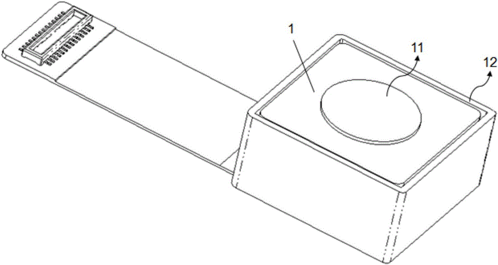
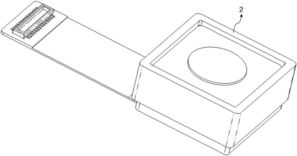
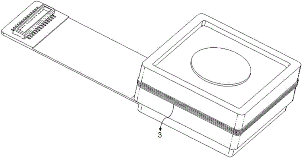
[0053] combine Figure 1-Figure 6 , the integrated structure of the camera and the NFC antenna of the present invention is described in detail, which includes: a camera module 1 and an NFC antenna 3, wherein the side of the camera module 1 is provided with a magnetic conductive material 2; on the magnetic material 2. In this embodiment, the NFC antenna further includes an encapsulation structure, and the encapsulation structure is an encapsulant sprayed onto the NFC antenna 3 for encapsulating the NFC antenna 3 .

[0054] like figure 1 The general structural diagram shown in the figure includes: a camera functional module 11 and a camera housing 12 . The camera housing 12 is arranged around the outside of the camera functional module 11 and exposes the front of the camera functional module 11 . The camera functional module 11 mainly includes a lens group, which is composed of one or more lenses, an optical filter, and an image sensor. Some functional modules also include a V...

Embodiment 2

[0061] The difference between this embodiment and Embodiment 1 is that the setting positions of the magnetic conductive material 2 and the NFC antenna are different. Figure 11 Describing it in detail, the magnetic conductive material 2 of this embodiment is arranged on the top of the camera module 1, which is arranged in a ring shape and does not block the camera of the camera module 1, such as Figure 8a As shown, the projection of the magnetically conductive material 2 and the projection of the camera housing 12 may or may not overlap, such as Figure 8b The top view when overlapping is shown, as Figure 8c Shown is a top view without overlapping; the NFC antenna 3 is arranged above the magnetically conductive material 2, as shown in Figure 9 shown; then encapsulate the NFC antenna 3 by dispensing, such as Figure 10 shown.

[0062] like Figure 11 Shown is a schematic diagram of installing the integrated structure of this embodiment into a mobile terminal, only the ca...

Embodiment 3

[0065] This embodiment describes the working method of the integrated structure of the camera and the NFC antenna of the present invention in detail. Only one of the camera module 1 and the NFC antenna 2 is working at the same time, which includes the following steps:

[0066] S11: When the NFC antenna is turned on, determine whether the camera module is turned on. If the camera module is turned on, turn off the camera module, and then turn on the NFC antenna. If the camera module is not turned on, turn on the NFC antenna directly;

[0067] It also includes step 13: when the camera module is turned on, it is determined whether the NFC antenna is turned on, if the NFC antenna is turned on, the operation is ended, and if the NFC antenna is not turned on, the camera module is turned on. Steps S11 and S13 are in no particular order.


PUM


Abstract

The invention discloses a camera and antenna integrated structure and a working method thereof. The structure comprises a camera module and an antenna, wherein a magnetic conduction material is arranged outside the camera module, the antenna is arranged on the magnetic conduction material. A first method comprises the following steps of judging whether the camera module is opened or not when the antenna is opened, if yes, closing the camera module and opening the antenna, otherwise directly opening the antenna; and judging whether the antenna is opened or not when the camera module is opened, if yes, completing operation, otherwise opening the camera module. Or a second method comprises the following steps of judging whether the antenna is opened or not when the camera module is opened, if yes, closing the antenna and opening the camera module, otherwise directly opening the camera module; and judging whether the camera module is opened or not when the antenna is opened, if yes, completing operation, otherwise opening the antenna. The camera and the antenna are integratedly designed, and the camera and antenna integrated structure is compact and is low in cost.

Description

technical field [0001] The present invention relates to the technical field of communication, in particular to an integrated structure and working method of a camera and an antenna. Background technique [0002] In the existing electronic products, the camera and the antenna are separate product structures, and the chips and firmware of the two work independently. This product structure has active shortcomings, such as: (1) under the trend of increasingly thin and compact mobile phones, the design of two independent structures is easily limited, and the product performance is not good; (2) two independent structure forms, the product The unit price is higher. [0003] Therefore, there is an urgent need to provide a compact and low-cost electronic product with a camera and a communication or charging antenna at the same time. SUMMARY OF THE INVENTION [0004] In view of the problems existing in the above-mentioned prior art, the present invention proposes an integrated st...

Claims


Application Information

Patent Timeline
Patent Type & Authority Applications(China)
IPC IPC(8): H01Q1/22
CPCH01Q1/22
Inventor 李立忠陈德智陈鹏
Owner SHANGHAI AMPHENOL AIRWAVE COMM ELECTRONICS CO LTD
Why Eureka
Try Eureka