
Rapid positioning transferring method for electronic assembly bearing disc

A technology of electronic components and carrying trays, applied in the direction of electrical components, electrical components, etc., can solve the problems of slow running speed, stop, and limited carrying capacity of the conveyor belt

Active Publication Date: 2016-07-06
致茂电子(苏州)有限公司
View PDF5 Cites 0 Cited by
  • Summary
  • Abstract
  • Description
  • Claims
  • Application Information

AI Technical Summary

Problems solved by technology

[0003] Among them, although the conveyor belt (conveyer) is used to carry the electronic component carrier plate, although it has a high carrying capacity, the speed of the conveyor belt is usually not fast, and it is impossible to directly position the electronic component carrier plate and stay in a fixed working position. It is necessary to temporarily stop the conveyor belt or otherwise disengage the electronic component carrier from the conveyor belt
On the other hand, the electronic components must be transferred in batches by the shuttle, which cannot be carried continuously like a conveyor belt, so its carrying capacity is limited

Method used


Image

  • Rapid positioning transferring method for electronic assembly bearing disc
  • Rapid positioning transferring method for electronic assembly bearing disc
  • Rapid positioning transferring method for electronic assembly bearing disc

Examples


Embodiment Construction

[0040] Before the rapid positioning and transfer method of the electronic component carrying tray of the present invention is described in detail in this embodiment, it should be noted that in the following description, similar components will be represented by the same component symbols.

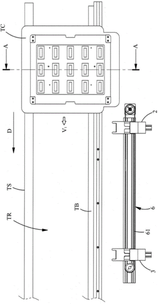
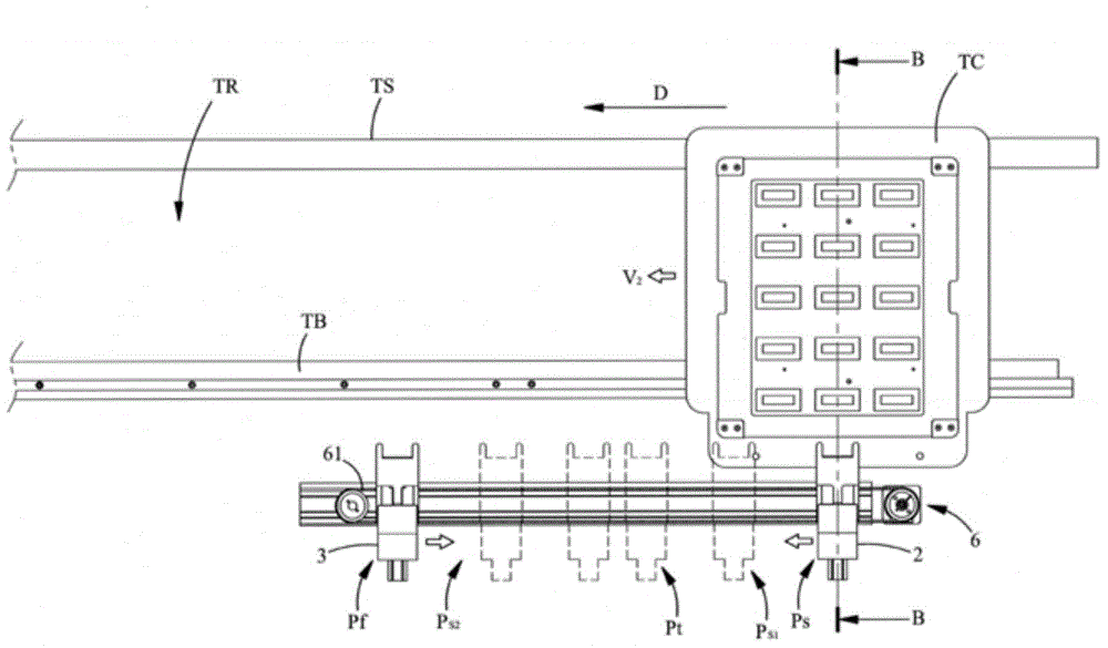
[0041] Please also see figure 1 ,and figure 2 , figure 1 It is a schematic top view of a preferred embodiment of the present invention, figure 2 It is a schematic top view showing the working position of a preferred embodiment of the present invention. As shown in the figure, this embodiment is used to match a transport track TR, but not limited thereto, and the transport track TR transfers an electronic component carrier tray TC in a predetermined direction D. Referring to FIG. In this embodiment, the conveying track TR mainly includes a conveying belt TB and a supporting member TS, wherein the rotation of the conveying belt TB drives the displacement of the electronic component carry...


PUM


Abstract

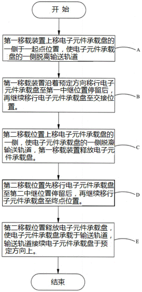
The invention discloses a rapid positioning transferring method for an electronic assembly bearing disc. One side of the electronic assembly bearing disc is transferred through a first transferring device to separate from a conveying track, the electronic assembly bearing disc is transferred at the first half stroke, secondly, the electronic assembly bearing disc is transferred through a second transferring device, after the electronic assembly bearing disc is borne from the first transferring device, the electronic assembly bearing disc is transferred through the second half stroke, and the electronic assembly bearing disc returns to the conveying track at the terminal point. According to the method, the electronic assembly bearing disc is transferred through the two transferring devices, the rapid removing effect is realized, extra waiting time waste is avoided, segment positioning for the two transferring devices in the transferring process can be realized, and the multi-station stop effect can be realized.

Description

technical field [0001] The invention relates to a fast positioning and transferring method for an electronic component carrier tray, in particular to a transfer method suitable for transferring and positioning the electronic component carrier tray. Background technique [0002] In the fields of manufacturing, testing and packaging of electronic components, it is common to load the electronic components on the carrier tray, and use the transfer carrier tray to transport the electronic components. However, in the prior art, currently more common equipment for transporting the carrier trays is nothing more than a conveyor belt (conveyer), or a guide rail combined with a shuttle (shuttle) to carry the electronic components. [0003] Among them, although the conveyor belt (conveyer) is used to carry the electronic component carrier plate, although it has a high carrying capacity, the speed of the conveyor belt is usually not fast, and it is impossible to directly position the ele...

Claims


Application Information

Patent Timeline
Patent Type & Authority Applications(China)
IPC IPC(8): H05K13/02
Inventor 温启明张添登
Owner 致茂电子(苏州)有限公司
Learn More