
Method and system for identifying operating states of a vehicle, and a vehicle which comprises such a system

一种运行状态、车辆的技术,应用在制动安全系统、制动器等方向

Active Publication Date: 2016-07-06
ZF CV SYST EURO BV
View PDF9 Cites 2 Cited by
  • Summary
  • Abstract
  • Description
  • Claims
  • Application Information

AI Technical Summary

Problems solved by technology

[0008] The methods and devices known from the prior art have the disadvantage that they can only be used under certain conditions or conditions, namely when, for example, special braking systems or special valves are available

Method used


Image

  • Method and system for identifying operating states of a vehicle, and a vehicle which comprises such a system
  • Method and system for identifying operating states of a vehicle, and a vehicle which comprises such a system
  • Method and system for identifying operating states of a vehicle, and a vehicle which comprises such a system

Examples


Embodiment Construction

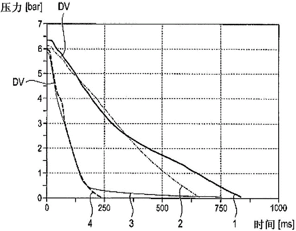
[0061] figure 1 A pressure-time diagram is shown, wherein a plurality of time-pressure curves DV of the vehicle are shown in the diagram. Pressure values ​​on the pressure axis are specified in SI units [bar] and time values ​​on the time axis are specified in [ms].

[0062]In the figure a total of four different time-pressure curves 1, 2, 3, 4 are shown in the case of venting of the vehicle's trailer control connection, in particular the pneumatic control line, i.e. one after releasing the vehicle's handgrip One is the time pressure curve DV after actuating the valve, and the other is the time pressure curve after a defined pressure loading of the control connection and after subsequent venting of the control connection to the surroundings or atmosphere. The trailer control connection is designed in particular as a pneumatic control line and is part of the vehicle's pneumatic system and is also configured by means of a trailer control valve for coupling to the pneumatic syst...


PUM


Abstract

The invention relates to a method for identifying an operating state of a vehicle, said operating state being selected from at least one first or second operating state, and the vehicle comprising a pneumatic braking system and a pneumatic control connection that is designed to connect said pneumatic braking system to a further pneumatic braking system of a trailer, and the method comprising the following steps: applying pressure to the control connection until a starting pressure is set in said control connection; opening the control connection such that pressure is compensated between the control connection and a surrounding environment; acquiring a temporal pressure curve during this pressure compensation process; comparing said temporal pressure curve to a reference pressure curve; determining an evaluation result based on the comparison of the temporal pressure curve and the reference pressure curve; and assigning this evaluation result to the first or the second vehicle operating state. The invention also relates to an electro-pneumatic system, and to a vehicle.

Description

technical field [0001] The invention relates to a method for detecting the operating state of a vehicle, in particular with or without a trailer, according to independent claim 1 , an electropneumatic system according to another independent claim 14 and a vehicle according to claim 15 . Background technique [0002] The detection of the operating state of the vehicle, in particular whether the trailer is coupled to a (commercial) vehicle, for example a truck (truck truck), is usually carried out or queried in the prior art by means of a CAN connection between the vehicle and the trailer or by means of corresponding CAN signals. However, there are also vehicles and trailers that do not have such a CAN connection. It is also possible that the CAN connection is defective, or that only the vehicle or the trailer respectively has a CAN connection, so that a status query of the vehicle via the CAN connection is not possible. [0003] Therefore, it is desirable, in addition to or ...

Claims


Application Information

Patent Timeline
Patent Type & Authority Applications(China)
IPC IPC(8): B60T17/22
CPCB60T17/22B60T8/323B60T13/268B60T13/683B60T8/1708B60T8/171
Inventor 克里斯托夫·巴尔特托比亚斯·蒙科英戈·塔
Owner ZF CV SYST EURO BV
Learn More