Medical soft tissue suturing device

A suturing device and soft tissue technology, applied in applications, surgical instruments, etc., can solve the problems of not having a double-joint multi-joint linkage propulsion mechanism, not meeting the needs of clinical operations, inconvenient to use, etc., to achieve convenient use, avoid damage to nerves and Bones, effects for easy assembly

Inactive Publication Date: 2016-07-13
南京英麦德医疗科技有限公司 +1
5 Cites 1 Cited by

AI-Extracted Technical Summary

Problems solved by technology

[0002] Existing suturing devices do not have a dual or multi-linkage propulsion mechanism. After the needle passes through the tissue, it is pulled back to catch the front hair anchor, which is a one-time consumption. However, it is often necessary to pass through the soft tissue multiple times during the operation. Determine the optimal position, so th...

Method used

Compared with the propeller of existing propulsion structure, the design of protrusion and limit hole in the present invention can accurately control the position of advancing thimble 6, the design of groove 202, seam 103 and hand push plate 302, The present invention is convenient to use, accurate in propulsion and accurate in positioning.
[0054] In order to facilitate the advancement of the sliding device 3, the end of the hand push plate 302 close to the needle tube fixing member 4 is bent upwards, specifically referring to the bent portion 3021 in FIG. 5 . In the present invention, the designed bending angle ranges from 10° to 50° (angle α in FIG. 2-2 ). In this angle, the push plate 302 is easier to push and saves effort.
[0068] In the present invention, due to the design of the angle α (Fig. 2-2) of the bent portion 3021 and the design of the engraving or bump (mark 3022 in Fig. 3), not only the advancement of the sliding device 3 is more labor-saving , and the ad...

Abstract

The invention relates to a medical soft tissue suturing device which comprises a soft tissue suturing needle part and a flexible and elastic limiting and propelling part. A needle is a part for puncturing soft tissue needing to be sutured, the flexible and elastic limiting and propelling part propels an ejector pin, one end of the ejector pin and the flexible and elastic limiting and propelling part are fixed together, and the other end of the ejector pin freely slides in a needle tubing under the action of hand thrust. The ejector pin pushes an implanted anchor needle left in the soft tissue needing to be sutured to enter the soft tissue needing to be sutured. The device cannot touch the deep layer of the soft tissue easily in the use process by determining multiple parameter ranges, more labor is saved for propelling of the device, and the propelling range of a sliding device is controllable. By means of design of protrusions and limiting holes, the position of the propelling ejector needle can be accurately controlled. By means of design of a groove, a spigot and a hand pushing plate, the medical soft tissue suturing device is convenient to use, accurate in propelling and precise in locating. By means of the medical soft tissue suturing device, suturing can be completed effectively, accurately and more safely.

Application Domain

Suture equipments

Technology Topic

Suture needlesBiomedical engineering +3

Image

  • Medical soft tissue suturing device
  • Medical soft tissue suturing device
  • Medical soft tissue suturing device

Examples

  • Experimental program(1)

Example Embodiment

[0046] The preferred embodiments of the present invention are given below in conjunction with the accompanying drawings to describe the technical solution of the present invention in detail.
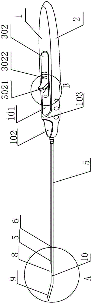
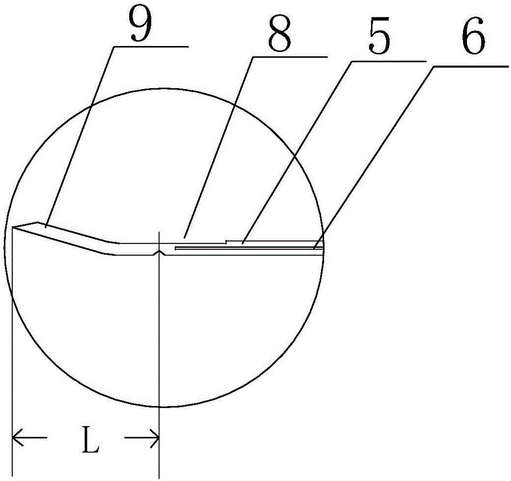
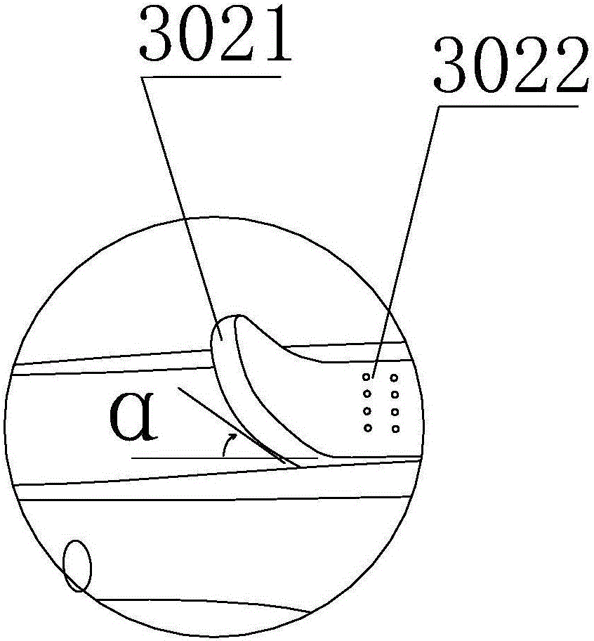
[0047] figure 1 It is a schematic diagram of the overall structure of the present invention, Figure 2-1 for figure 1 Enlarged view at "A", Figure 2-2 for figure 1 Enlarged view of "B", image 3 It is a structural schematic diagram of the soft elastic limit propulsion part in the present invention, Pic 4-1 It is a structural schematic diagram of the propulsion sliding device installed in the groove of the lower shell in the present invention, Figure 4-2 for Pic 4-1 Enlarged view at "C". As shown in the above figure: the present invention includes a soft tissue suturing needle part and a soft elastic limit advancing part; the needle 9 in the soft tissue suturing needle part is the part that punctures the soft tissue that needs to be sutured.
[0048] The flexible and elastic limit advancing part includes a shell, a needle tube fixing part 4, and a pusher slide device 3, and the pusher slide device 3 includes a pusher slide 301 and a hand push plate 302. The push slide 301 and the hand push plate 302 are integrally formed; the push slide 301 is As a part that slides in the housing, the hand push plate 302 is the part where fingers touch.
[0049]The outer shell includes an upper shell 1 and a lower shell 2; the outer surface of the upper shell 1 is provided with a long hole 101 for the push plate 302 to move on the outer surface of the upper shell 1 and a small hole 102 in the upper shell for clamping the needle tube fixing member 4; the lower shell 2 is provided with a groove 201, and the pusher 301 can slide in the groove 201; the lower casing 2 has a small hole 202 in the lower casing corresponding to the upper casing 1 for clamping the needle tube fixing member 4.
[0050] A number of protrusions 7 are provided at the position where the pusher slider 301 contacts the groove 201 of the lower shell 2, and the groove 201 is provided with a number of limit holes corresponding to the protrusions 7 (not shown in the figure); or: push The position of the sliding member 301 in contact with the groove 201 of the lower case is provided with a plurality of limiting holes, and the groove 201 is provided with a plurality of protrusions 7 corresponding to the limiting holes.
[0051] In the specific application of the present invention, both sides of the groove 201 include limit holes, and corresponding parts (both sides) of the pusher slider 301 in contact with the groove 201 are provided with a corresponding number of protrusions 7 .
[0052] The propulsion sliding device 3 is a propulsion sliding device made of elastically deformable material, the groove 201 of the lower shell 2 is a groove made of an elastically deformable material, and the use of the elastically deformable material can facilitate the use of the propulsion sliding device 3. forward and backward.
[0053] Push the hand push plate 302, the push slide 301 integrated with the push plate 302 moves in the groove 201 of the lower shell 2, and further drives the thimble 6 fixed with the push slide 301 to move in the needle tube 5, when the protrusion 7 enters the limit When the hole (not shown in the figure) is opened, the ejector pin 6 reaches a desired position.
[0054] In order to facilitate the advancement of the advancing sliding device 3, one end of the hand push plate 302 close to the needle tube fixing member 4 is bent upwards. For details, please refer to Figure 5 Bent portion 3021 in . In the present invention, the designed bending angle range is 10-50° ( Figure 2-2 angle α) in which the push plate 302 is easier and less laborious to advance.
[0055] In order to further facilitate hand pushing, the upper surface of the hand push plate 302 is fixed with engravings or bumps ( image 3 Marking 3022 in ), similarly, the needle tube fixing member 4 is provided with bumps or engravings ( image 3 Note 401 in ). In the present invention, through experimental verification, the number of protrusions 7 can generally be selected as 2-5, and the number of corresponding limit holes can also be selected as 2-5. When using 3 protrusions and The best effect is achieved with matching limit holes. In actual operation, the number of protrusions and limit holes can be set by yourself according to the different needs of the soft tissue to be sutured.
[0056] In actual use, the distance between adjacent protrusions 7 is in the range of 3-6mm (see Figure 4-2 "M" in the); the range of the distance between the corresponding adjacent limit holes is: 3-6mm. The range of the distance from the limit groove 10 to the topmost section of the needle 9 is: 2.5~6.5mm (see Figure 2-1 "L" in the ); the distance from the opening 8 to the topmost section of the needle 9 is: 20-50mm (see Image 6 "N" in ). Between the long hole 101 on the outer surface of the upper shell 1 and the small hole 102 of the upper shell 1, there is a stop 103 for preventing the hand push plate from being pushed forward excessively.
[0057] The flexible elastic limit push part pushes the thimble in the needle part of the soft tissue suture, one end of the thimble 6 is fixed with the pusher slide 301, and the other end slides freely in the needle tube under the action of hand push; on one side of the penetrating anchor.
[0058] The flexible elastic limit advancing part pushes the thimble in the needle part of the soft tissue suture, and then pushes the implantable anchor needle left in the soft tissue to be sutured into the soft tissue to be sutured.
[0059] Image 6 It is a schematic structural diagram of the soft tissue suture needle part in the present invention before the thimble is advanced. Figure 7 for Image 6 top view. like Figure 6-7 Shown: the soft tissue suture needle part includes needle 9, needle tube 5, limit groove 10, posterior anchor 14, anterior anchor 15 and thimble 6. Anterior anchor 15 and posterior anchor 14 are required for suturing implantable anchors in soft tissue (see Figure 9 ), the needle 9 is the part that punctures the soft tissue that needs to be sutured, the needle tube 5 is a hollow tube, and the part close to the needle 9 on the needle tube 5 is provided with an opening 8; the limit groove 10 is opened on the needle tube 5 and is close to the end of the needle 9; thimble 6 By pushing the sliding member 301 in the needle tube 5, one end of the thimble 6 is pressed against one side of the rear anchor 14, the other side of the rear anchor 14 is close to the front anchor 15, and the rear anchor 14 and A gap is left between the front hair anchor pins 15 .
[0060] Before the entire medical soft tissue suturing device with multi-joint mechanism performs soft tissue suturing, the thimble 6 , the posterior anchor 14 and the anterior anchor 15 are all located on the same side of the limiting groove 10 away from the needle 9 .
[0061] In order to achieve the best limiting effect, in the specific implementation process of the present invention, the width of the limiting groove is selected as 0.5-1.5 mm, and the height of the limiting groove is selected as 0.1-1 mm.
[0062] In order to facilitate assembly and disassembly, the needle tube fixing member 4 is provided with bumps or engravings 401 that increase friction to facilitate disassembly. When assembling, first install the pusher slide 301 of the pusher slide device 3 in the groove 201 of the lower shell 2, then pass the thimble 6 through the needle tube 5, clamp the needle tube fixing member 4 on the small hole 202 of the lower shell, and finally put the upper The case 1 covers the lower case 2 .
[0063] Compared with the pusher of the existing pusher structure, the design of the protrusion and the limiting hole in the present invention can accurately control the position of the pusher pin 6, and the design of the groove 202, the stop 103 and the hand push plate 302 makes the present invention It is easy to use, accurate in propulsion and precise in positioning.
[0064] When suturing, first, the needle 9 can be used to repeatedly puncture the soft tissue according to the needs of the operation, find the position to be sutured, and push the hand push plate 302. Because of the function of the protrusion 7 and the corresponding limit hole, the position of the thimble 6 is not adjusted. If it will be pushed too far, push the front anchor 15 through the limit slot 10, and leave the front anchor 15 in the desired part of the soft tissue. Use the needle 9 again to find a new position, and push the push plate after finding a new suture position. 302 to push the thimble 6, at this moment, the protrusion 7 moves in the direction of the needle 9, the protrusion 7 is inserted into the corresponding limit hole again, and the thimble 6 pushes out the posterior anchor 14, leaving the posterior anchor 14 in the soft tissue required parts.
[0065] The distance from the limit groove 10 to the topmost section of the needle 9 is: 2.5-6.5mm; in the current common products of the same kind, the distance from the limit groove 10 to the topmost section of the needle 9 is about 10mm. In the present invention, the length is shortened, Compared with the existing similar products, the needle in the present invention is shorter, and it is less likely to touch the deep layers of the soft tissue during use, thereby avoiding damage to nerves and bones.
[0066] In the present invention, the spacing range between adjacent protrusions 7 is: 3-6 mm; the spacing range between corresponding adjacent limiting holes is: 3-6 mm. In the present invention, the distance range between the adjacent protrusions 7 and the distance range between the adjacent limit holes are based on the distance range of the gap between the rear anchor pin 14 and the front anchor pin 15 and the limit The range of the distance between the groove 10 and the topmost section of the needle 9 is determined, in order to make the back anchor 14 and the front anchor 15 in the device of the present invention shorter than the distance from the common limiting groove 10 to the top of the needle 9 For ejection, the present invention designs the distance range between the adjacent protrusions 7 and the distance range between the corresponding limiting holes.
[0067] In the present invention, the distance “N” from the opening 8 to the topmost section of the needle 9 is in the range of 20-50 mm. The distance to the top is within a reasonable range, and in the present invention, the back hair anchor pin 14 (without ejection, in the Image 6 state) and the leftmost end of opening 8 (see Image 6 ) can be adjusted appropriately.
[0068] In the present invention, due to the angle α of the bent portion 3021 ( Figure 2-2 ) design and engraving or embossing ( image 3 The design of the mark 3022 in (3022) not only makes the pushing of the sliding device 3 more labor-saving, but also makes the pushing range of the sliding device 3 in a controllable state.
[0069] Compared with the pusher of the existing pusher structure, the needle tube fixing member 4 and the needle tube 5 in the present invention are integrally formed, and the pusher sliding member 301 and the hand push plate 302 are integrally formed, which facilitates assembly, reduces maintenance, and is more convenient to use.
[0070] Figure 8 For a schematic diagram of the soft tissue portion to be sutured, Figure 9 Schematic diagram of the procedure for suturing soft tissue sections. like Figure 8 and 9 Shown: the distance range of the gap between the rear anchor pin 14 and the front anchor pin 15 is 0.5-3mm. In the actual field application process, the above size range can be adjusted according to the field use situation.
[0071] During suturing, after the soft tissue is pierced by the needle of the suturing device, the thimble 6 is used to push the front anchor needle over the limit groove, and when withdrawn, the soft tissue hangs on the front anchor needle 15, and then the soft tissue 16 to be sutured is sutured by tightening the suture 17. .
[0072] When using the present invention, the rear anchor pin 14 and the front anchor pin 15 are placed behind the limiting groove 10, such as Image 6 and 7 In the middle, the posterior anchor 14 and the anterior anchor 15 are placed on the left side of the limiting groove 10. During suture, there are suture areas on both sides of the suture opening 11 on the soft tissue 18 to be sutured. In the present invention, the needle can repeatedly puncture the soft tissue according to the needs of the operation, until the optimal suture position is found, and then the implantable anchor needle left in the soft tissue to be sutured is advanced. In the present invention, the anchors are artificially and subjectively advanced, and multiple anchors are repeatedly advanced in the same manner, and finally the soft tissue is sutured. The use of the present invention can effectively, accurately and safely complete the suture.
[0073] The basic principles and main features of the present invention and the advantages of the present invention have been shown and described above. Those skilled in the art should understand that the present invention is not limited by the above-mentioned embodiments. The above-mentioned embodiments and descriptions only illustrate the principle of the present invention. Without departing from the spirit and scope of the present invention, the present invention will also have Various changes and improvements fall within the scope of the claimed invention, which is defined by the appended claims and their equivalents.

PUM

PropertyMeasurementUnit
Width range0.5 ~ 1.5mm
Height range0.1 ~ 1.0mm

Description & Claims & Application Information

We can also present the details of the Description, Claims and Application information to help users get a comprehensive understanding of the technical details of the patent, such as background art, summary of invention, brief description of drawings, description of embodiments, and other original content. On the other hand, users can also determine the specific scope of protection of the technology through the list of claims; as well as understand the changes in the life cycle of the technology with the presentation of the patent timeline. Login to view more.

Similar technology patents

Household appliance control method and device and mobile terminal

InactiveCN103605531Aeasy to operateeasy to use
Owner:GD MIDEA AIR-CONDITIONING EQUIP CO LTD +1

Macrocyclic picolinamides as fungicides

ActiveUS20140187588A1good performanceeasy to use
Owner:CORTEVA AGRISCIENCE LLC

System and method of monitoring temperature

InactiveUS7140768B2less susceptible to tampereasy to use
Owner:COLD CHAIN TECH

Wireless charging transmitter, receiver, charging device and wireless charging method

ActiveCN104158269ASimple codingeasy to use
Owner:湖南长城科技信息有限公司 +1

Classification and recommendation of technical efficacy words

  • easy to use

Laser assisted total joint arthroplasty

InactiveUS20090234360A1easy to use
Owner:ALEXANDER VLADIMIR

Enclosure for a portable hemodialysis system

ActiveUS20090114582A1easy to use
Owner:DEKA PROD LLP
Why Eureka
Try Eureka