Supercharge Your Innovation With Domain-Expert AI Agents!

Tool setting gauge for numerical control machine tool

A technology of CNC machine tool and tool setting instrument, which is applied in the direction of automatic control devices, metal processing machinery parts, metal processing, etc., can solve the problems of affecting the accuracy of tool setting, spring parts are easy to fail, etc., and achieve the effect of accurate reset and long life

Inactive Publication Date: 2016-07-13
邓海程
View PDF6 Cites 1 Cited by
  • Summary
  • Abstract
  • Description
  • Claims
  • Application Information

AI Technical Summary

Problems solved by technology

[0003] In order to solve the defects in the prior art that spring parts are prone to failure and affect the accuracy of tool setting, the present invention provides a tool setting instrument for CNC machine tools that can improve tool setting accuracy and prolong service life

Method used


Image

  • Tool setting gauge for numerical control machine tool
  • Tool setting gauge for numerical control machine tool

Examples


Embodiment Construction

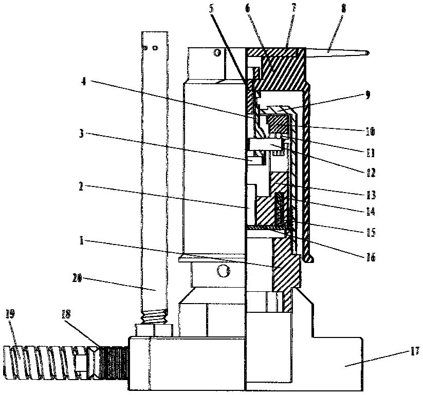
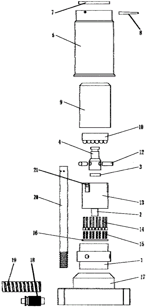
[0012] Such as figure 1 with figure 2 As shown, the CNC machine tool setting instrument consists of base 17, cable 19, gas circuit connector 18, lamp holder 1, gas column 20, magnetic core 2, probe 14, spring 15, probe holder 13, circuit board 16, magnetic Sheet 3, copper rod 12, copper rod holder 4, inner cover 9, tungsten steel sheet 7, stylus 8 and outer cover 6.

[0013] The lamp holder 1 is installed at the center of the upper part of the base 17, and the cable 19 and the gas joint 18 are installed on the side of the base 17. An upright air column 20 is installed next to the lamp holder 1 on the upper part of the base 17. The air connection 18 is in communication with the air column 20.

[0014] The probe holder 13 is installed on the lamp holder 1 and connected and fixed with the inner cover 9. The probe holder 13 has a cylindrical blind cavity inside, and three opening slots 20 are evenly distributed on the side walls of the blind cavity. The outer bottom plane of the p...


PUM


Abstract

The invention discloses a tool setting gauge for a numerical control machine tool. A probe and a copper ball are fixedly arranged inside an inner housing; a movable copper bar is arranged between the probe and the copper ball; each of the copper bar and the probe is provided with a magnetic piece. A mutually repulsive space is formed between the copper bar and the probe by using a repulsion principle of poles N and S of magnets; when the copper bar needs to be reset after displacement, the copper bar is accurately reset under the action of a stable linear repulsion force of the magnets; in addition, since the magnets are long in life and do not need to be frequently replaced, the tool setting gauge is also long in life.

Description

Technical field [0001] The invention relates to a numerical control machine tool accessory device, in particular to a numerical control machine tool setting instrument. Background technique [0002] The CNC machine tool setting instrument is a device installed on the fixed table of the machine tool to calibrate the zero point setting. The internal structure of the traditional tool setting instrument is the same as that described in the patent document CN2923170Y, that is, the contact head is set with a spring, and a non-contact sensor is arranged under the probe under the contact head. When the contact head and its probe are vertically displaced, the position is adjusted by the sensor. When the signal is transmitted, the machine tool automatically adjusts the tool position according to the tool setting signal to realize the tool setting operation. Because the spring of the tool setting instrument has a certain service life, the elasticity will decrease over time, increase the er...

Claims


Application Information

Patent Timeline
IPC IPC(8): B23Q15/22
CPCB23Q15/22
Inventor 邓海程
Owner 邓海程
Features
  • R&D
  • Intellectual Property
  • Life Sciences
  • Materials
  • Tech Scout
  • Unparalleled Data Quality
  • Higher Quality Content
  • 60% Fewer Hallucinations
Learn More