
Separate quantitative pump head and its pump bottle

A separate, fixed-quantity pump technology, which is applied in the direction of closing, packaging, and individual handheld devices, can solve the problems of increasing hand grip, power consumption, and volume increase, and achieves improved connection stability, increased contact area, and simplified removal. The effect of using the method

Active Publication Date: 2018-01-02
仇霖
View PDF6 Cites 0 Cited by
  • Summary
  • Abstract
  • Description
  • Claims
  • Application Information

AI Technical Summary

Problems solved by technology

However, for the pharmaceutical packaging industry, there are strict requirements on the capacity of medicines, and it is still impossible to control the amount of liquid obtained by each extrusion
Therefore, in order to solve this problem, the structure of the cap is generally improved, or an additional quantitative valve is set to achieve precise control of the output liquid volume, but this will inevitably cause the structure of the entire bottle cap to be complicated, and the corresponding The volume of the device has also increased. With the above-mentioned overall structure, users need to hold a bottle no matter whether they are taking liquid or using it, which increases the grip strength of the hand.
[0005] Whether it is to use the soft and compressible characteristics of the container to press the container to take the liquid and use it, or to use the installed quantitative valve to take the liquid quantitatively and then use it, it is relatively labor-intensive. The above-mentioned problems in the use of the liquid after taking the liquid are undoubtedly will affect the user experience

Method used


Image

  • Separate quantitative pump head and its pump bottle
  • Separate quantitative pump head and its pump bottle
  • Separate quantitative pump head and its pump bottle

Examples


Embodiment Construction

[0066] In order to more clearly illustrate the embodiments of the present invention or the technical solutions in the prior art, the specific implementation manners of the present invention will be described below with reference to the accompanying drawings. Obviously, the accompanying drawings in the following description are only some embodiments of the present invention, and those skilled in the art can obtain other accompanying drawings based on these drawings and obtain other implementations.

[0067] In order to make the drawing concise, each drawing only schematically shows the parts related to the present invention, and they do not represent the actual structure of the product. In addition, to make the drawing simple and easy to understand, the arrows indicate the direction of movement.

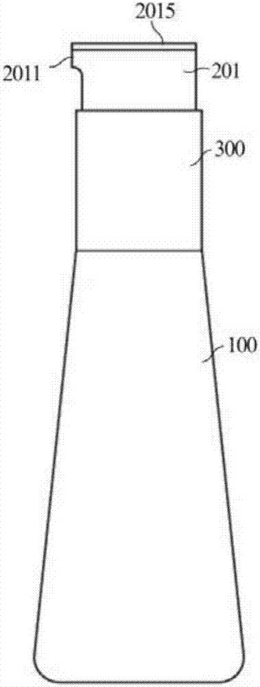
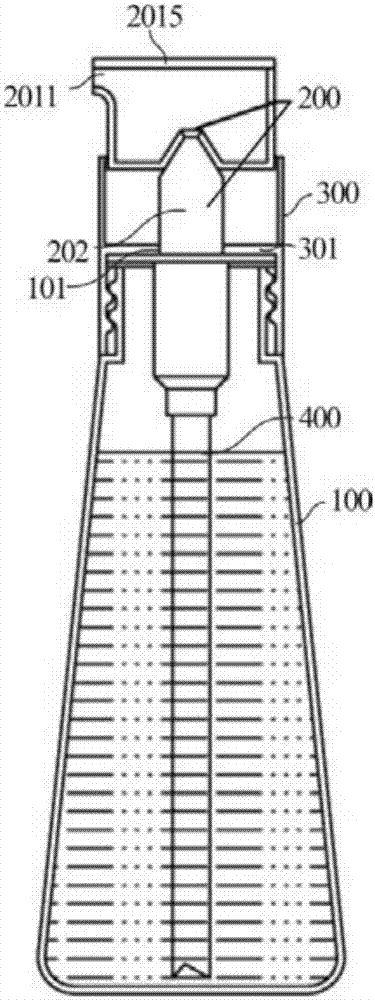
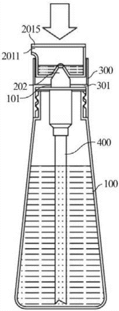
[0068] In Embodiment 1 of the separate quantitative pump head of the present invention, see Figure 1-13 , a separate quantitative pump head, the pump head includes a pressing part ...


PUM


Abstract

The invention provides a separated type quantitative pump head which comprises a pressing part.The pressing part comprises a pressing head and a pressing rod.A liquid outlet is formed in the top end of the pressing head.A through hole penetrates through the bottom face of the pressing head.The edge of the through hole extends towards the top end of the pressing head to form an extension edge.A liquid storage space capable of containing liquid is formed between the extension edge and the inner wall of the pressing head.One end of the pressing rod abuts against the interior of the through hole and is in interference fit with the extension edge.The pressing head is detachably assembled and sealed on the pressing rod.When bearing pressure, liquid enters the liquid storage space of the pressing head through the pressing head.The invention further provides a pump pressure cylinder with a separated type quantitative pump.The use experience of consumes can be improved through a split type design simplifying and using method, the precision of the output liquid volume can be effectively improved, and applied liquid can be separated and quantitatively taken for use.

Description

technical field [0001] The invention relates to a pump device, in particular to a separate quantitative pump head and a pump bottle thereof. Background technique [0002] The existing liquid packaging bottle is for the convenience of taking liquid, and avoids a lot of liquid that is likely to appear when pouring directly from the open type, resulting in waste. [0003] At present, there is a container bottle with simple structure and convenient operation. The soft and compressible characteristics of the container are used to press the container, the compressed internal air overflows to the opening, and the liquid is sprayed out by the overflow air. The amount of spray is determined by the size of the pressing force. It is determined that sometimes too much liquid is ejected too vigorously, and sometimes the amount of liquid ejected is insufficient, and even the liquid cannot be ejected. All of these situations cause the user to use too little force, resulting in insufficien...

Claims


Application Information

Patent Timeline
Patent Type & Authority Patents(China)
IPC IPC(8): B65D47/34
CPCB05B11/061
Inventor 仇霖
Owner 仇霖
Learn More