Elevator speed limiter

A technology of elevator speed limiter and electromagnet, which is used in elevators, transportation and packaging, etc., can solve the problem of insufficient reliability of the solution for rolling cars, and achieve the effect of preventing rolling cars and improving reliability.

Active Publication Date: 2016-07-13
LANGFANG JIULIAN MACHINERY CO LTD
View PDF10 Cites 3 Cited by
  • Summary
  • Abstract
  • Description
  • Claims
  • Application Information

AI Technical Summary

Problems solved by technology

[0007] Therefore, the technical problem to be solved by the present invention is that the reliability of the car rolling solution in the prior art is insufficient

Method used


Image

  • Elevator speed limiter
  • Elevator speed limiter
  • Elevator speed limiter

Examples


Embodiment 1

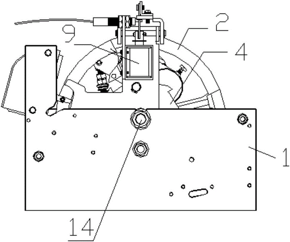
[0037] This embodiment provides a speed governor for an elevator, comprising a sheave 2, which is rotatably arranged in the box body 1 around a first rotating shaft 14 and has a groove 20, a part protrudes from the opening 21, and the first rotating shaft The two ends of 14 are fixed on the corresponding box walls of the box body 1; the steel wire rope 3 is wound tightly in the groove of the sheave 2, connected to the car of the elevator, and drives the car to move synchronously with it; the ratchet 4 , set coaxially with the sheave 2, the limit device is used to limit the rotation angle of the ratchet 4; the linkage device is arranged between the ratchet 4 and the sheave 2, and is used for sliding the car , linking the ratchet 4 and the sheave 2.

[0038] The sheave 2 moves synchronously with the car through the wire rope 3, and the ratchet 4 limits the rotation angle of the ratchet 4 itself through the limiting device. When the car stops at a certain floor, the linkage devi...

Embodiment 2

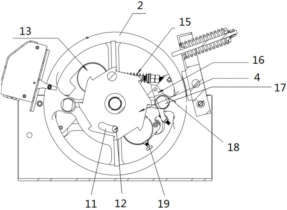
[0050] This embodiment provides an elevator speed governor, which is a further improvement on the basis of Embodiment 1.

[0051] Such as figure 2 As shown, the elevator speed governor also includes an overspeed linkage device, and the overspeed linkage device includes

[0052] The two throwing blocks 13 are arranged symmetrically with respect to the first rotating shaft, and the two throwing blocks 13 are connected together by linkage pull rods, and are gathered to the mandrel of the sheave through the coil spring 15;

[0053] The rotating shaft 17 is vertically arranged on the sheave;

[0054] The pawl 16 is rotatably arranged on the rotating shaft 17;

[0055] The spring 18 is arranged between the ratchet 16 and the sheave, and provides the force for the ratchet 16 to rotate away from the ratchet 4 .

[0056] When the sheave rotates at an overspeed, the throwing block 13, under the action of centrifugal force, overcomes the force of the coil spring 15, expands and moves...


PUM


Abstract

The invention provides an elevator speed limiter. A rope wheel and a car synchronously move through a steel wire rope; a ratchet wheel limits a self rotating angle through a limiting device. When the car stops at a certain floor, a linkage device is started, so that the ratchet wheel is in linkage with the rope wheel; at the moment, once a car sliding phenomenon occurs, the limiting device firstly limits the rotating range of the ratchet wheel; at the moment, as the ratchet wheel is in linkage with the rope wheel, the rotation of the rope wheel is also limited, and the rope wheel and the car synchronously move through the steel wire rope arranged on the rope wheel in a tensioning manner; after the rotation of the rope wheel is limited, the steel wire rope of the speed limiter lifts and pulls a safety clamp operating handle, a safety clamp brakes the elevator car, and the motion of the car is also limited, so that the effect of controlling car sliding is realized. According to the elevator speed limiter, a phenomenon in the prior art that the car cannot stop due to the simple control of braking of a traction machine (as the secondary braking of the traction machine is not tight) can be effectively avoided.

Description

technical field [0001] The invention relates to the technical field of elevator speed governors, in particular to an elevator speed governor, in particular to a speed governor capable of preventing an elevator from slipping. Background technique [0002] The speed limiter is a part of the elevator overspeed protection device. The speed limiter is installed in the machine room at the top of the elevator, and the tensioning device is installed in the pit at the bottom of the elevator. The steel wire rope is looped between the speed limiter and the tensioning device in a closed loop. The tensioning device makes the steel wire rope tightly wrapped in the speed governor. , so that the speed limiter and the elevator car move synchronously at all times. [0003] Elevator overspeed is generally the phenomenon that the upward or downward speed of the elevator exceeds 115% of the rated speed. When the elevator is overspeed, under the action of the centrifugal force generated by the ...

Claims


Application Information

Patent Timeline
Patent Type & Authority Applications(China)
IPC IPC(8): B66B5/04
CPCB66B5/04
Inventor 柳树林龙勇
Owner LANGFANG JIULIAN MACHINERY CO LTD
Why Eureka
Try Eureka