Drying mechanism and washing machine

A drying mechanism, fan motor technology, applied in the washing machine field, to achieve the effect of reducing performance

Active Publication Date: 2016-07-13
SUZHOU SAMSUNG ELECTRONICS CO LTD +1
7 Cites 3 Cited by

AI-Extracted Technical Summary

Problems solved by technology

The thermostat can only cut off the protection when the temperature of the hot air at the outlet of the air duct is abnormally high. When the temperature of the hot air at the...

Method used

In addition, the protection concept of the present invention is based on prevention, utilizes centrifugal switch 4 to just cut off heater 3 before the heat accumulation of air duct, thereby can protect drying mechanism before comparatively serious heating phenomenon takes place Compared with the protection of the thermostat 2 in the prior art, the partial damage caused by high temperature to the performance of the machine and some parts is reduced.
In order to facilitate installation, in the drying mechanism provided by the foregoing embodiments, the air duct is formed by butting the upper cover 7 and the lower cover 8, which is convenient for overhauling parts such as the heater 3, the fan, and the fan motor 5 in the air duct.
[0032] The above-mentioned thermostat 2 is preferably two, respectively located on both sides of the heater 3. The present invention sets two automatic disconnection points on the heating circuit 11 through two thermostats 2, and when one of the thermostats 2 fail...

Abstract

The invention provides a drying mechanism which comprises an air duct, a heater, a fan, a fan motor, a circuit control board and a centrifugal switch for controlling a heating circuit to be connected or disconnected, wherein the circuit control board is provided with the heating circuit for controlling the heater to be on or off and a motor circuit for controlling the fan motor to be on or off; the heating circuit is in parallel connection with the motor circuit, the heater is in series connection with the heating circuit, and the fan motor is in series connection with the motor circuit; and the centrifugal switch is in series connection with the heating circuit and is coaxially connected with the fan motor. When the fan motor rotates, the centrifugal switch is switched on, and when the fan motor stops rotating, the centrifugal switch is switched off. Only on the premise that the fan motor rotates can the heater work. When the circuit control board starts the fan motor and the fan motor cannot rotate due to faults, the centrifugal switch cannot be switched on, and the heater cannot perform heating normally. It is guaranteed that the problem that only the heater works, so that the severe local heating is caused and the drying mechanism is burned down is solved, and hidden fire danger is reduced. The invention further provides a washing machine.

Application Domain

Washing machine with receptaclesTextiles and paper +1

Technology Topic

ElectricityElectric machine +2

Image

  • Drying mechanism and washing machine
  • Drying mechanism and washing machine
  • Drying mechanism and washing machine

Examples

  • Experimental program(1)

Example Embodiment

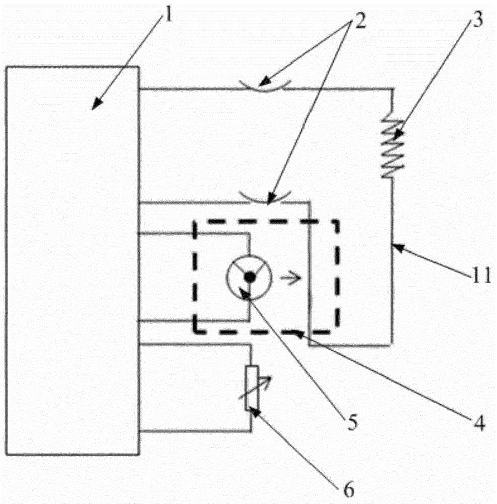
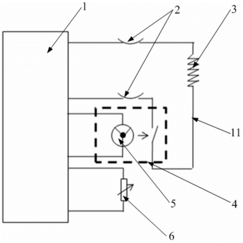
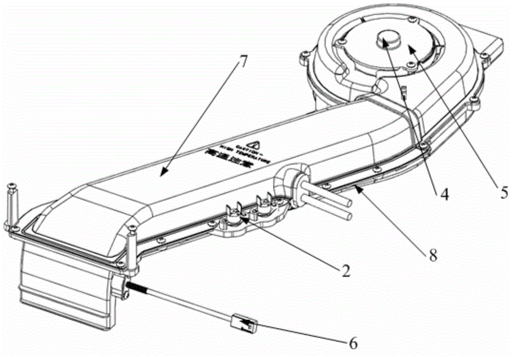
[0026] The embodiment of the present invention provides a drying mechanism, which can avoid excessively high temperature of the drying mechanism when the fan motor is not working, thereby reducing the hidden danger of fire.
[0027] In order to make the objectives, technical solutions, and advantages of the embodiments of the present invention clearer, the technical solutions in the embodiments of the present invention will be described clearly and completely in conjunction with the accompanying drawings in the embodiments of the present invention. Obviously, the described embodiments It is a part of the embodiments of the present invention, not all the embodiments. Based on the embodiments of the present invention, all other embodiments obtained by those of ordinary skill in the art without creative work shall fall within the protection scope of the present invention.
[0028] Please refer to the attached Figure 1-4 The drying mechanism provided by the embodiment of the present invention includes an air duct, a heater 3, a fan, a fan motor 5, a circuit control board 1 and a centrifugal switch 4; wherein the heater 3 is arranged in the air duct; the fan is arranged at the inlet of the air duct The fan motor 5 is used to drive the fan to rotate; the circuit control board 1 is provided with a heating circuit 11 that controls the opening and closing of the heater 3 and a motor circuit that controls the opening and closing of the fan motor 5. The heating circuit 11 is set in parallel with the motor circuit, and the heater 3 is connected in series to the heating circuit 11, and the fan motor 5 is connected in series to the motor circuit; the centrifugal switch 4 can control the on and off of the heating circuit 11, and the centrifugal switch 4 is connected in series to the heating circuit 11 and coaxially connected with the fan motor 5. The centrifugal switch 4 is closed when 5 is rotating, and the centrifugal switch 4 is opened when the fan motor 5 stops rotating.
[0029] In the above drying mechanism, after the circuit control board 1 controls the fan motor 5 and the heater 3 to work, when the fan motor 5 rotates, the centrifugal force generated by it will close the centrifugal switch 4, the heating circuit 11 is turned on, and the heater 3 can be normal Work like figure 1 As shown; also when the fan motor 5 stops rotating, the centrifugal force disappears, the centrifugal switch 4 is disconnected, and the heating circuit 11 is also disconnected. The heater 3 cannot work and cannot heat, such as figure 2 Shown. In this way, the heater 3 of the present invention can work only when the wind power motor 5 is rotating. When the circuit control board 1 starts the fan motor 5 and the fan motor 5 fails to rotate, the centrifugal switch 4 cannot be closed, and the heater 3 Therefore, heating cannot be performed normally; in this way, it is ensured that only the heater 3 works and causes severe local heating and burns the drying mechanism, so that the temperature of the drying mechanism can be avoided when the fan motor 5 is not working If it is too high, it reduces the fire hazard and effectively protects the life and property of consumers.
[0030] In addition, the protection concept of the present invention focuses on prevention. The centrifugal switch 4 is used to cut off the heater 3 before the heat in the air duct accumulates, so that the drying mechanism can be protected before a more serious heating phenomenon occurs. The protection of the thermostat 2 in the prior art reduces partial damage to the performance of the machine and some parts caused by high temperature.
[0031] Preferably, the drying mechanism further includes a temperature sensor 6 for detecting the temperature of the hot air at the outlet of the air duct and sending a temperature signal; a thermostat 2 for receiving the temperature signal and controlling the opening and closing of the heater 3 according to the temperature of the hot air, When the temperature of the hot air is higher than the preset temperature, the thermostat 2 controls the heater 3 to turn off. When the temperature of the hot air is lower than the preset temperature, the thermostat 2 controls the heater 3 to turn on, and the thermostat 2 is connected in series to the heating circuit 11. And connected with the temperature sensor 6. When the washing machine is running the drying program, the temperature sensor 6 will detect the temperature of the hot air at the outlet of the air duct. When the temperature of the hot air at the outlet of the air duct is higher than the preset temperature, the thermostat 2 will control the heater 3 to automatically turn off. Thus, the heater 3 is cut off, which can prevent the temperature from being too high during the drying process, and improve the safety and reliability.
[0032] There are preferably two temperature controllers 2 described above, which are located on both sides of the heater 3 respectively. The present invention uses two thermostats 2 to set two automatic disconnect points on the heating circuit 11. When one of the thermostats 2 fails, the other thermostat 2 can also be used to disconnect the heating circuit 11. To improve safety and reliability. Of course, the above-mentioned thermostat 2 can also be one. Alternatively, the present invention can also use the circuit control board 1 to control the heater 3 to automatically turn off.
[0033] In a specific embodiment of the present invention, the centrifugal switch 4 is built in the fan motor 5 and is an integral structure with the fan motor 5. The present invention can adopt the method with the smallest modification in the prior art-replacing the fan motor 5 with the centrifugal switch 4, the centrifugal switch 4 is built in the fan motor 5, and then the centrifugal switch 4 is connected to the wiring harness of the heating circuit 11 , Easy to modify. It should be noted that the contacts of the centrifugal switch 4 of the present invention are made of materials resistant to high current and high voltage, which improves the service life and safety.
[0034] In order to facilitate installation, in the drying mechanism provided in the above embodiment, the air duct is formed by butting the upper cover 7 and the lower cover 8, which facilitates the maintenance of the heater 3, the fan, and the fan motor 5 in the air duct.
[0035] An embodiment of the present invention also provides a washing machine, including a drying mechanism, which is the drying mechanism provided in any one of the above embodiments, which can prevent the drying mechanism from overheating when the fan motor is not working , Thereby reducing the hidden danger of fire, and its advantages are brought by the drying mechanism. For details, please refer to the relevant parts in the above-mentioned embodiments, which will not be repeated here.
[0036] The various embodiments in this specification are described in a progressive manner. Each embodiment focuses on the differences from other embodiments, and the same or similar parts between the various embodiments can be referred to each other.
[0037] The foregoing description of the disclosed embodiments enables those skilled in the art to implement or use the present invention. Various modifications to these embodiments will be obvious to those skilled in the art, and the general principles defined herein can be implemented in other embodiments without departing from the spirit or scope of the present invention. Therefore, the present invention will not be limited to the embodiments shown in this document, but should conform to the widest scope consistent with the principles and novel features disclosed in this document.

PUM

no PUM

Description & Claims & Application Information

We can also present the details of the Description, Claims and Application information to help users get a comprehensive understanding of the technical details of the patent, such as background art, summary of invention, brief description of drawings, description of embodiments, and other original content. On the other hand, users can also determine the specific scope of protection of the technology through the list of claims; as well as understand the changes in the life cycle of the technology with the presentation of the patent timeline. Login to view more.

Similar technology patents

Power supply system, control method thereof and electronic equipment

PendingCN114679053AAvoid excessive inrush currentreduce performance
Owner:GUANGDONG OPPO MOBILE TELECOMM CORP LTD

Liquid ejection head and manufacturing method thereof

PendingUS20220032625A1reduce performancereduce manufacturing yield
Owner:CANON KK

Method for forming semiconductor device

ActiveCN105448813Areduce adverse effectsreduce performance
Owner:SEMICON MFG INT (SHANGHAI) CORP

Hang correction in a power management interface bus

ActiveUS20220058154A1reduce performanceintroduce latency
Owner:QUALCOMM INC

Control system for service robot

InactiveCN110587634Areduce performancesimple design
Owner:SHENZHEN SANBOT INNOVATION INTELLIGENT CO LTD

Classification and recommendation of technical efficacy words

  • reduce performance

Compositions comprising a fluoroolefin

InactiveUS20060243944A1reduce performance
Owner:EI DU PONT DE NEMOURS & CO

Approach for Reducing Injector Fouling and Thermal Degradation for a Multi-Injector Engine System

ActiveUS20080017171A1improve charge cool effectreduce performance
Owner:FORD GLOBAL TECH LLC +1

Methods and apparatus for managing operations of a web browser

InactiveUS20120260181A1reduce performanceimprove operation
Owner:QUALCOMM INNOVATION CENT

Thermal blanket including a radiation layer

InactiveUS20050208851A1reduce performanceincrease thermal resistivity
Owner:HALE NICHOLAS

Video display apparatus and video display method

InactiveUS20050151883A1reduce performancecorrect irregularity
Owner:TOSHIBA VISUAL SOLUTIONS CORPORATION
Why Eureka
Try Eureka