Auxiliary wrench for valve

A wrench and valve technology, applied in valve details, valve device, valve operation/release device, etc., to achieve the effect of simple structure, practical convenience, and inconvenience solving

Inactive Publication Date: 2016-07-13
天津汉光祥云信息科技有限公司
View PDF0 Cites 0 Cited by
  • Summary
  • Abstract
  • Description
  • Claims
  • Application Information

AI Technical Summary

Problems solved by technology

But unscrewing the valve once it needs to be repaired becomes a big problem
Especially for the valves at h

Method used


Image

  • Auxiliary wrench for valve

Examples


Example Embodiment

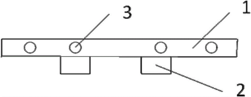
[0010] The valve auxiliary wrench in this embodiment includes a round pipe handle 1, a movable sleeve 2 and a screw hole 3 provided on the side of the round pipe handle. The movable sleeve 2 is located directly below the round pipe handle 1, and is passed through a screw Fixed at the screw hole 3.

[0011] The valve auxiliary wrench of this embodiment can adjust the position of the movable sleeve to cover the general valve switch in the movable sleeve, and then turn the round pipe handle to easily turn the valve. The structure of the invention is simple and practical. Convenient, greatly solving the inconvenience caused by valve problems during maintenance.

[0012] An embodiment of the present invention has been described in detail above, but the content is only a preferred embodiment of the present invention, and cannot be considered as limiting the scope of implementation of the present invention. All equal changes and improvements made in accordance with the scope of the appli...


PUM

PropertyMeasurementUnit
Diameteraaaaaaaaaa
Lengthaaaaaaaaaa

Abstract

The invention provides an auxiliary wrench which comprises a round tube handle, a movable sleeve and a screw hole formed in the side of the round tube handle. According to the auxiliary wrench for the valve, by adjustment of the position of the movable sleeve, an ordinary valve switch is sleeved with the movable sleeve, and the valve can be switched easily through the rotation of the round tube handle. The auxiliary wrench is simple in structure, practical and convenient, and the problem of inconvenience caused by valve problems during overhauling is solved well.

Description

technical field [0001] The invention relates to the mechanical field, in particular to a valve auxiliary wrench. Background technique [0002] With the progress of society and the improvement of living standards, factories, units, and residential buildings are full of various pipelines, and countless large and small valves are also installed. For the sake of safety and convenience, the valves are not only screwed very tightly, but also placed relatively close to the corners, such as the valves at the sewer pipes, such as the tower valves of the factory. But unscrewing the valve once it needs maintenance becomes a big problem. Especially for the valves at home, if you can't unscrew them, you have to call the maintenance company, which is expensive and troublesome. Contents of the invention [0003] The problem to be solved by the present invention is to provide a suggestion device that can make people easily unscrew the valves that require more effort. [0004] To solve ...

Claims


Application Information

Patent Timeline
IPC IPC(8): F16K31/60
Inventor 朱爱民聂凯吴昊梁丽杰
Owner 天津汉光祥云信息科技有限公司
Why Eureka
Try Eureka