Water-cooled air conditioner water treatment system
A technology of water treatment system and water-cooled air conditioner, applied in air-conditioning system, space heating and ventilation, space heating and ventilation details, etc., can solve the problem of inconvenient movement of water-cooled air-conditioning water treatment system, achieve convenience when moving and avoid damage , the effect of convenience and comfort
- Summary
- Abstract
- Description
- Claims
- Application Information
AI Technical Summary
Problems solved by technology
Method used
Image
Examples
Embodiment 1
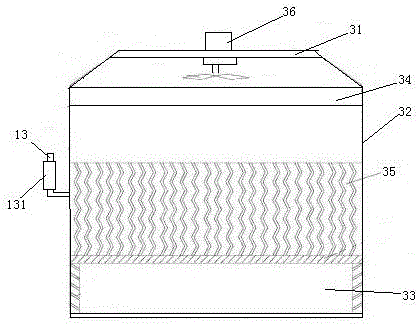
[0024] Embodiment one, see figure 1 , a water-cooled air-conditioning water treatment system includes a box surrounded by a top cover 31 at the top, a frame 32 at the middle and a water tank 33 at the bottom. The top cover 31 is equipped with a fan 36 . A water distributor 34 is arranged below the top cover 31 . The side wall of the frame 32 is provided with a water curtain 35 . The frame 32 is provided with a handle bar 13 . The outer elastic sleeve of the handle bar 13 is provided with a sleeve 131 .
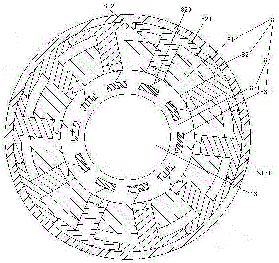
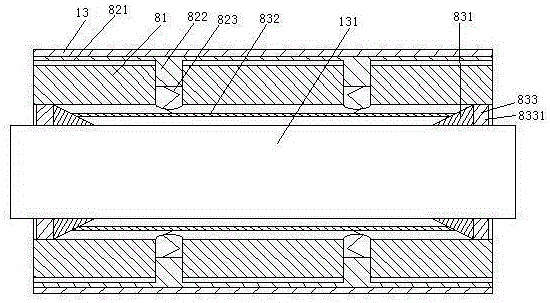
[0025] see figure 2 , An elastic force adjustment mechanism 8 is provided between the handle bar 13 and the sleeve 131 . The elastic force adjustment mechanism 8 includes a base pipe 81 , a clamping layer 82 and a preload adjustment structure 83 . The base pipe 81 is sheathed outside the handle bar 13 . The base pipe 81 passes through the casing 131 . The clamping layer 82 is composed of several friction strips 821 . The friction strips 821 are distributed along the ...
Embodiment 2
[0029] Embodiment two, the difference with embodiment one is:
[0030] see Figure 4 , The fan 36 is provided with a wire inlet and outlet 37 and a pipe head 38. Pipe head 38 is affixed together with wire inlet and outlet 37 by jacking bolt 39.
[0031] see Figure 5 , The inner end of the pipe head 38 is provided with a spherical head 381 . A spherical cavity 371 is provided on the inner wall of the wire inlet and outlet 37 . The pipe head 38 is clamped in the spherical cavity 371 through the spherical head 381 and is hinged together with the wire inlet and outlet 37, that is, the pipe head 38 and the wire inlet and outlet 37 are spherically fitted to be hinged. There is a clearance fit between the spherical head 381 and the spherical cavity 371 . The spherical head 381 and the spherical cavity 371 are connected together through a supporting ring 383 . The support ring 383 is fixedly connected to the wire inlet and outlet 37 . All the free ends 382 of the spherical head ...
Embodiment 3
[0034] Embodiment three, the difference with embodiment two is:
[0035] see Figure 6 , The water tank 33 is provided with supporting feet 9. The support foot 9 is provided with a buried section installation hole 95 . The lower end of the installation hole 95 of the buried section is provided with an inner flange 951 . The installation holes in the buried section are threaded holes. A buried section 94 is inserted in the installation hole 95 of the buried section so that it can be pulled up upwards. The upper end of the buried section 94 is provided with a protruding ring 941 . The protrusion ring 941 cooperates with the inner flange 951 to prevent the buried section 94 from falling off downward. An extruded pipe 96 is threadedly connected in the installation hole 95 of the buried section. The lower end of the buried section 94 is provided with a gripping structure 4 . The gripping structure 4 includes a pressing rod 41 , a limiting member 45 and two oppositely arrange...
PUM
 Abstract
Description
Claims
Application Information
 - R&D
- Intellectual Property
- Life Sciences
- Materials
- Tech Scout
- Unparalleled Data Quality
- Higher Quality Content
- 60% Fewer Hallucinations
Browse by: Latest US Patents, China's latest patents, Technical Efficacy Thesaurus, Application Domain, Technology Topic, Popular Technical Reports.
© 2025 PatSnap. All rights reserved.Legal|Privacy policy|Modern Slavery Act Transparency Statement|Sitemap|About US| Contact US: help@patsnap.com


