Laser ranging system and method based on waveform time domain matching

A laser ranging and waveform technology, applied in the field of measuring instruments, can solve the problems of large trigger time fluctuations and low intermediate frequency phase distance measurement method test speed, etc. The effect of visual effects

Active Publication Date: 2016-07-13
SUTENG INNOVATION TECH CO LTD
View PDF8 Cites 33 Cited by
  • Summary
  • Abstract
  • Description
  • Claims
  • Application Information

AI Technical Summary

Problems solved by technology

[0004] The object of the present invention is to provide a laser ranging system and method based on waveform time-domain matching, which effectively overcomes the large fluctuations in trigger time caused by the trigger threshold of the TDC (time-to-digital converter) system with different echo amplitudes. It also solves the test rate problem of the low-IF phase-based ranging method

Method used


Image

  • Laser ranging system and method based on waveform time domain matching

Examples


Embodiment Construction

[0021] The present invention will be further described below in conjunction with the accompanying drawings and specific embodiments.

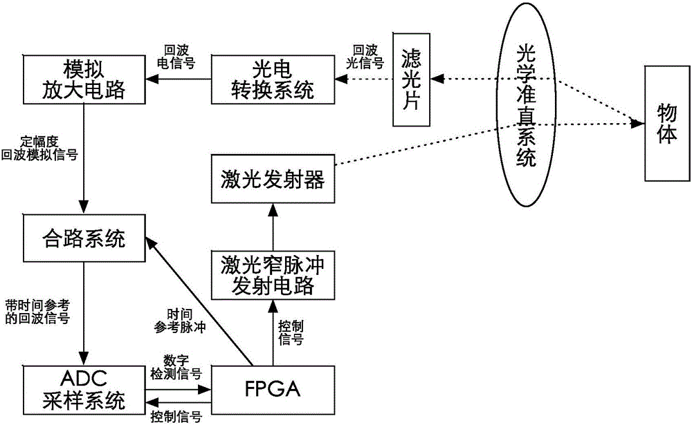
[0022] attached figure 1 It is a structural block diagram of the pulsed laser ranging system based on waveform time-domain matching in the present invention, and the system includes a software part and a hardware part.

[0023] The hardware part includes optical collimation system, FPGA, filter, photoelectric conversion system, analog amplifier circuit, laser transmitter, signal combination system, ADC sampling system and laser narrow pulse emission circuit; the FPGA sends control signals to the laser narrow pulse Pulse emission circuit, the emission circuit controls the laser transmitter to emit pulsed laser; the laser is emitted to the object through the optical collimation system, and the object reflects the laser through the optical collimation system and optical filter to transmit the echo optical signal to the photoelectric conversion sys...


PUM


Abstract

The invention discloses a laser ranging system and method based on waveform time domain matching. The laser ranging system includes software and hardware, and is characterized in that an FPGA sends a control signal to a laser narrow pulse transmission circuit; the transmission circuit controls a laser transmitter to transmit pulse laser; an object reflection laser beam transmits an echo wave optical signal to a photo-translating system through an optical alignment system and a spike filter; the photo-translating system converts an optical signal into an echo wave electric signal, and then the echo wave electric signal becomes a fixed amplitude echo wave analog signal through an analog amplification circuit and enters a signal integration system; when the FPGA transmits a control signal to control laser transmission, at the same time, the FPGA transmits a time reference pulse to the signal integration system; the signal integration system integrates the time reference pulse and the fixed amplitude echo wave analog signal into an echo wave signal with time reference; the echo wave signal with time reference is quantified as a digital detection signal in an ADC sampling system, and then is transmitted to the FPGA for data analysis; and a ranging result is output from the FPGA by means of analysis of waveform time domain matching of the software part.

Description

technical field [0001] The invention relates to the technical field of measuring instruments, in particular to a pulse laser ranging system and method. Background technique [0002] The basic principle of pulse laser ranging is to actively emit pulse laser to the target, then detect the laser echo of the irradiated point on the target, measure the flight time of pulse laser, and obtain the distance from the target to the rangefinder. The ranging accuracy of pulsed laser ranging is determined by the measurement accuracy of laser time of flight. Because the pulsed laser is affected by the atmosphere and the scattering characteristics of the target, the laser echo has great differences in amplitude and shape, and the resulting time drift error makes it difficult to accurately determine the laser echo time. At present, there are four main methods for laser echo time identification: frontier identification method, constant ratio identification method, high-pass capacitive resist...

Claims


Application Information

Patent Timeline
Patent Type & Authority Applications(China)
IPC IPC(8): G01S17/08G01S7/487G01S17/10
CPCG01S7/487G01S17/08G01S7/4866G01S7/4868G01S7/484G01S17/10G01S17/42H03M1/12
Inventor 邱纯鑫刘乐天
Owner SUTENG INNOVATION TECH CO LTD
Why Eureka
Try Eureka