
Moving target tracking method based on optical flow

A moving target and optical flow technology, which is applied in the field of optical flow-based moving target tracking, can solve problems such as limited tracking accuracy

Inactive Publication Date: 2016-07-13
XIAN UNIV OF TECH
View PDF3 Cites 17 Cited by
  • Summary
  • Abstract
  • Description
  • Claims
  • Application Information

AI Technical Summary

Problems solved by technology

[0005] The purpose of the present invention is to provide a method for tracking a moving object based on optical flow, which improves the tracking accuracy of the object and solves the problem of limited tracking accuracy of the existing optical flow-based moving object tracking method

Method used


Image

  • Moving target tracking method based on optical flow
  • Moving target tracking method based on optical flow
  • Moving target tracking method based on optical flow

Examples


Embodiment Construction

[0057] The present invention will be further described in detail below in conjunction with the accompanying drawings and specific embodiments, but the present invention is not limited to these embodiments.

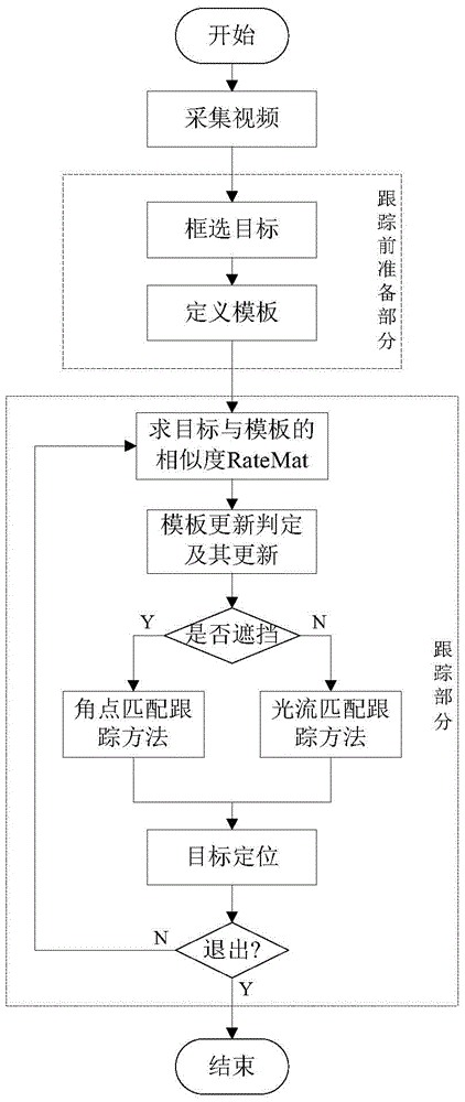
[0058] The present invention provides a moving target tracking method based on optical flow, the flow chart is as follows figure 1 As shown, the specific steps are as follows:

[0059] Step 1, collect video images, and prepare for tracking.

[0060] Step 1.1. Obtain video frame images from the camera or local files.

[0061] Step 1.2, do the preparatory work before tracking, including artificially selecting the target to be tracked and performing template definition and variable initialization, laying a solid foundation for subsequent tracking, specifically including the following steps:

[0062] Step 1.2.1. Manually select the target to be tracked. Since the target type cannot be known in advance, the selection of the tracked target is performed manually. After manuall...


PUM


Abstract

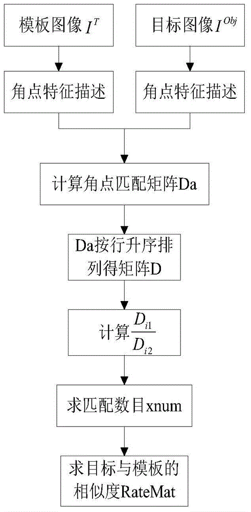
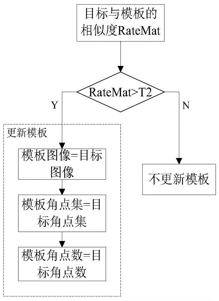
The present invention discloses a moving target tracking method based on an optical flow. The method comprises: collecting a video image, and performing the preparation work prior to tracking such as target selection, template definition, variable initialization and the like; calculating the similarity RateMat of the target and the template, determining whether the template is required to update or not according to the RateMat value, and if the template is required to update, the update of the template is carried out; performing shielding determination according to the RateMat value, employing a corner matching tracking method to track when the shielding happens, and employing the optical flow matching tracking method based on the technologies such as the corner position filtering, optimized contour determination, abnormal region determination and processing and the like to perform tracking; and determining whether the tracking is going on or not according to the tracking result, the tracking is end if the target position is out of the range or a target is reselected by people, or else, calculating the similarity RateMat of the target and the template again and performing iteration tracking. The moving target tracking method based on optical flow greatly improves the tracking precision of a target and solves the problem of limited precision of the optical flow in the moving target tracking method.

Description

technical field [0001] The invention belongs to the technical field of video monitoring, and in particular relates to a moving target tracking method based on optical flow. Background technique [0002] The concept of optical flow was first proposed by Gibson in 1950, and the calculation of optical flow was proposed by Horn and Schunck in 1981. The so-called optical flow is the instantaneous velocity of the pixel movement of the space moving object on the observation imaging plane. For the two frames of images I before and after in the video sequence t and I t+1 , the purpose of optical flow calculation is to obtain I t to I t+1 Motion vector between pixels in . The optical flow field calculation has the following assumptions: (1) The pixels are constant, that is, it is considered that two adjacent frames of images I t and I t+1 The colors between them are consistent (for grayscale images, the brightness is considered to be consistent); (2) the motion range is small, ...

Claims


Application Information

Patent Timeline
IPC IPC(8): G06T7/20
CPCG06T2207/30221G06T2207/10016G06T2207/20024
Inventor 赵凡张海燕姚怡景翠宁
Owner XIAN UNIV OF TECH
Learn More