Transfer device with path switching function

A technology of path switching and conveying devices, which is applied to the safety devices of the filling device, conveyors, and conveyor objects, etc., which can solve the problems of increased investment costs and achieve the effect of simple and cost-effective costs

Active Publication Date: 2016-07-13
SYNTEGON TECHNOLOGY GMBH
View PDF9 Cites 11 Cited by
  • Summary
  • Abstract
  • Description
  • Claims
  • Application Information

AI Technical Summary

Problems solved by technology

As a result, however, the investment costs for such a filling and packaging machine increase significantly

Method used


Image

  • Transfer device with path switching function
  • Transfer device with path switching function
  • Transfer device with path switching function

Examples


Embodiment Construction

[0021] Refer below Figures 1 to 5 A delivery device 1 according to a preferred embodiment of the present invention is described in detail.

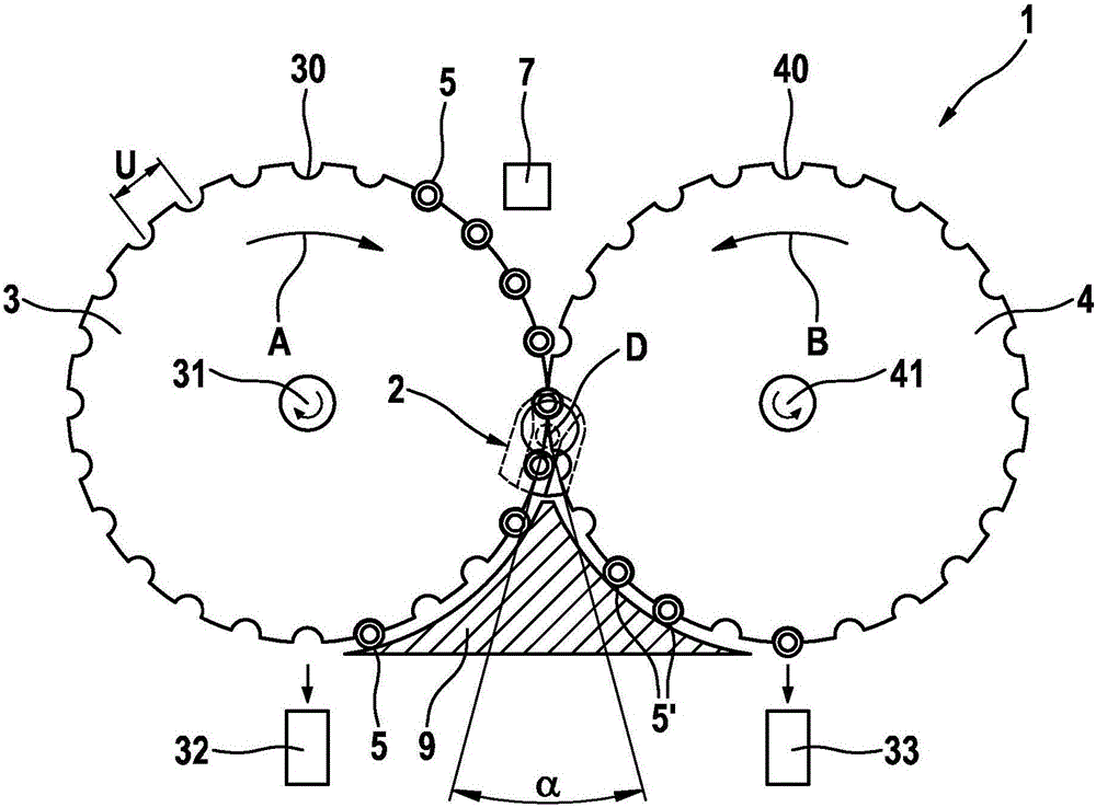
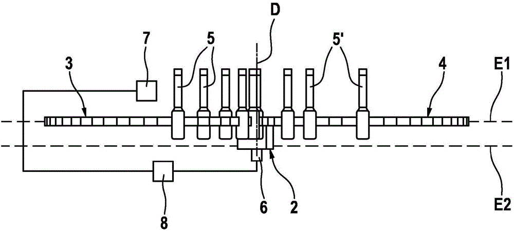
[0022] as by figure 1 and 3 As can be seen, the conveying device 1 comprises a first star wheel 3 and a second star wheel 4 . The conveying device 1 is used here to convey pharmaceutical containers 5 , which are designed as vials in the exemplary embodiment.

[0023] The containers 5 of pharmaceutical technology are guided to the first star wheel 3 via a further conveying device, not shown. The first star wheel 3 rotates in the direction of the arrow A here. The containers 5 pass here past a testing device 7 which, for example, checks the degree of filling of the containers 5 with, for example, powdered medicine or the like. If the container 5 has been filled to specification, the container 5 is conveyed to the dispensing station 32 next to the first star wheel 3 and there it is conveyed, for example, to a packaging unit. The trans...


PUM


Abstract

The invention relates to a transport device comprising a path switching device (2) for switching a transport path, a first star wheel (3), and a second star wheel (4). The path switching device (2) comprises a base part (20), a first jaw (21), and a second jaw (22), said two jaws (21, 22) defining a transport surface (23) between each other, wherein the path switching device (2) can be pivoted about a pivot axis (D), and the pivot axis (D) is parallel to a first central axis (31) of the first star wheel (3) and a second central axis (41) of the second star wheel (4).

Description

technical field [0001] The present invention relates to a conveying device having an improved path changing device for switching conveying paths. Background technique [0002] Different designs of delivery devices are known from the prior art. For example, star wheels are often used in the pharmaceutical field to carry out a change of direction or to carry out different process steps (such as filling, closing or the like) for transporting containers (eg vials or the like). In particular star wheels with vacuum technology can be used here, in which the containers to be transported are sucked into the slots within the star wheel and transported via the star wheel. To discharge the container, the vacuum is switched off and the container is transferred to another conveying means, for example another star wheel. Furthermore, devices are usually provided for rejecting defective products, for example due to insufficient filling or the like. For this purpose, it is known to use s...

Claims


Application Information

Patent Timeline
Patent Type & Authority Applications(China)
IPC IPC(8): B65G47/82B65G47/84
CPCB65G47/846B07C5/36B65B3/003B65B57/10B65G47/82B65G2201/0261B67C3/007
Inventor U·迈尔
Owner SYNTEGON TECHNOLOGY GMBH
Why Eureka
Try Eureka