
Rotor device for a vacuum pump, and vacuum pump

A vacuum pump and rotor technology, which is applied to the components of the pumping device for elastic fluid, the pump device, the pump, etc., can solve the problems of time-consuming and complicated connection methods, shorten the processing time, and ensure the effect of operation safety.

Active Publication Date: 2016-07-13
レイボルドゲーエムベーハー
View PDF4 Cites 1 Cited by
  • Summary
  • Abstract
  • Description
  • Claims
  • Application Information

AI Technical Summary

Problems solved by technology

This known connection method is time-consuming and complicated

Method used


Image

  • Rotor device for a vacuum pump, and vacuum pump

Examples


Embodiment Construction

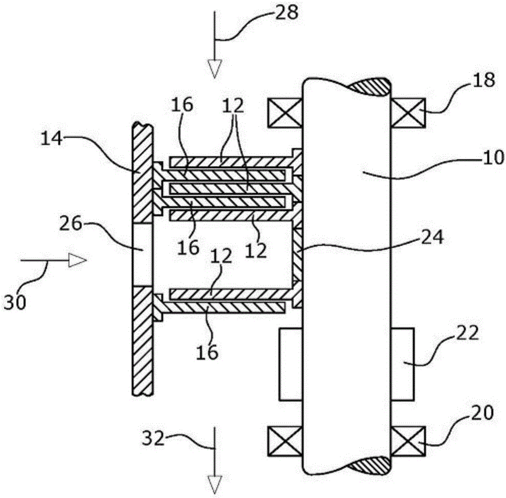
[0021] In a very simplified illustration of a turbomolecular pump, a plurality of rotor units 12 in the form of rotor disks are arranged on the shaft 10 by being pressed onto the shaft. Arranged in the pump housing 14 is a stator unit 16 , which may be a stator disk 16 in the embodiment shown.

[0022] The rotary shaft 10 is further supported in the pump housing 14 via bearing units 18 , 20 and driven by a drive 22 .

[0023] In the illustrated embodiment, a sleeve-like spacer unit 24 is further provided between the two rotor disks 12 . The intermediate inlet 26 is thus formed.

[0024] Thus, the vacuum pump shown schematically in the drawing draws the medium in the direction of arrow 28 to pass through the main inlet. Further, the medium is sucked in the direction of arrow 30 via the intermediate inlet 26 . The two media sucked in are delivered towards the outlet indicated by arrow 32 .

[0025] According to the invention, the shaft 10 is made of stainless steel in a pref...


PUM


Abstract

A rotor device for a vacuum pump comprises a rotor shaft (10) and at least one rotor element (12) on the rotor shaft (10). According to the invention, the at least one rotor element (12) contains aluminum, titanium and / or CFRP, while the rotor shaft (10) contains a chromium-nickel steel. This makes it in particular possible to join the at least one rotor element (12) to the rotor shaft (10) at room temperature using a pressing process.

Description

technical field [0001] The invention relates to a vacuum pump rotor device and a vacuum pump. Background technique [0002] Vacuum pumps such as turbomolecular pumps have, for example, a rotating shaft arranged in a pump housing. A shaft, typically driven by an electric motor, carries at least one rotor unit. In a turbomolecular pump, a plurality of rotor units in the form of rotor disks are arranged on a rotating shaft. The rotating shaft is rotatably supported in the pump casing via a bearing unit. Further, the vacuum pump has a stator unit arranged inside the housing. In a turbomolecular pump, a plurality of stator units formed as stator disks are provided. Here, stator disks and rotor disks are arranged alternately in the axial direction of the pump or in the flow direction of the medium to be pumped. [0003] For a rotor constructed from individual rotor disks, each rotor unit must be rigidly fixed to the shaft. A correspondingly strong, positionally precise conne...

Claims


Application Information

Patent Timeline
Patent Type & Authority Applications(China)
IPC IPC(8): F04D19/04F04D29/02F04D29/32
CPCF04D19/04F04D29/023F04D29/321F05D2300/43F05D2300/173F05D2300/174F05D2300/603F04D19/042F04D25/06
Inventor 马库斯·亨利尤尔根·布热齐纳罗伯特·施托勒彼得·科普
Owner レイボルドゲーエムベーハー
Learn More