
Toy top

A technology for gyroscopes and toys, applied in gyroscopes, toys, entertainment, etc., can solve the problems of easy wear and slow rotation of gyroscopes, and achieve the effects of reducing wear, reducing rotation speed, and increasing rotation speed

Inactive Publication Date: 2016-07-20
柳州市金旭节能科技有限公司
View PDF6 Cites 3 Cited by
  • Summary
  • Abstract
  • Description
  • Claims
  • Application Information

AI Technical Summary

Problems solved by technology

[0003] The technical problem to be solved by the present invention is to provide a toy top with reduced wear and higher speed in view of the shortcomings of existing toy tops, such as slow rotating speed and easy wear and tear.

Method used


Image

  • Toy top
  • Toy top

Examples


Embodiment 1

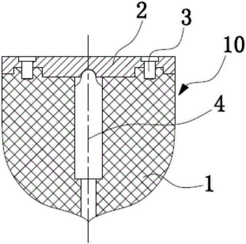
[0015] Such as figure 1 As shown, the toy top in this embodiment includes a revolving body 10. The upper part of the revolving body 10 is columnar and the lower part is conical. The revolving body 10 includes a main body 1 and a circular cover plate 2. Fixedly connected to the top of the main body 1. A shaft hole is provided in the middle of the main body 1, and the shaft hole runs through the main body 1 from the conical top of the lower conical part of the main body 1 along the central axis of the main body. The top of 4 is semicircular and is in contact with the bottom surface of cover plate 2 . In order to reduce the friction between the rotating shaft 4 and the main body 1, a lubricant, such as lubricating oil or carbon powder, is filled in the shaft hole.

[0016] In this embodiment, the rotating shaft 4 and the rotating body 10 can rotate with each other. When whipping the top with a whip rope, the rotating body 10 of the top rotates at a high speed. Since the frictio...

Embodiment 2

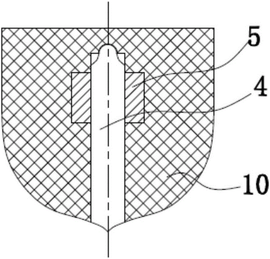
[0018] Such as figure 2 As shown, the toy top in this embodiment includes a revolving body 10, the upper part of which is columnar and the lower part is conical. A shaft hole is provided in the rotary body 10, and the shaft hole is set along the central axis of the rotary body from the cone top of the lower conical part of the rotary body 10. The upper end of the shaft hole is closed, and a rotating shaft 4 is arranged in the shaft hole, and the top of the rotating shaft 4 is semicircular. Shaped, contacting the rotating body 10 at the top of the shaft hole; In order to prevent the rotating shaft 4 from falling out of the shaft hole, a ring magnet 5 surrounding the shaft hole is arranged in the middle and upper part of the shaft hole. The central axis of the ring magnet 5 coincides with the central axis of the shaft hole, and the middle and upper part of the rotating shaft 4 has a ferromagnetic component , attract each other with the ring magnet. The lower half of the rotat...


PUM


Abstract

The invention relates to a toy top for solving the problems that an existing toy top is low in rotating speed and prone to abrasion.The toy top comprises a rotation body of which the upper portion is in a cylindrical shape and the lower portion is in a conical shape, a shaft hole with the closed upper end is formed in the central axis of the rotation body, a rotation shaft which can rotate relative to the rotation body is arranged in the shaft hole, and the lower end of the rotation shaft stretches out of the conical top of the rotation body.According to the toy top, the rotation shaft and the rotation body can mutually rotate, therefore, the rotational kinetic energy losses of the rotation body during toy top rotating can be reduced, the rotating speed of the rotation body can be increased, and the rotating time of the rotation body can be prolonged; meanwhile, the rotation body rotates relative to the rotation shaft, the rotating speed of the rotation shaft relative to the bottom face can be decreased, therefore, abrasion caused by friction between the rotation shaft and the bottom face can be reduced, and the service life of the rotation shaft can be prolonged; meanwhile, the rotation shaft can be replaced, and therefore the service life of the toy top can be prolonged by replacing the rotation shaft with a new one.

Description

technical field [0001] The present invention relates to a toy top, more specifically, to a toy top with a replaceable rotating shaft. Background technique [0002] As a fitness and entertainment equipment suitable for all ages, the toy top is widely loved by the public. The usual structure of the existing toy top is that the upper part is columnar, the lower part is conical, and the fulcrum of rotation is located at the top of the lower conical top. The fulcrum of the existing gyroscope is usually integrated with the gyroscope body, or is made of hard wear-resistant metal embedded in the fixed point of the lower part of the gyroscope body. Regardless of the structure, the fulcrum of the gyroscope rotates together with the gyroscope body. Due to the high speed of the gyro when it rotates, and the ground in contact with the fulcrum of the gyro is a hard and rough surface such as sand, cement, etc., the wear and tear on the fulcrum of the gyro is very large. Unable to stabili...

Claims


Application Information

Patent Timeline
Patent Type & Authority Applications(China)
IPC IPC(8): A63H1/00
CPCA63H1/00
Inventor 不公告发明人
Owner 柳州市金旭节能科技有限公司
Learn More