Steel pipe obliquely cutting device

A technology of oblique cutting and steel pipes, which is applied in the direction of pipe shearing device, shearing device, sawing machine device, etc., can solve the problems of high manufacturing cost and inconvenient operation, and achieve the effect of low manufacturing cost, convenient operation and high hardness

Active Publication Date: 2016-07-20
嘉兴小出钢管有限公司
View PDF6 Cites 12 Cited by
  • Summary
  • Abstract
  • Description
  • Claims
  • Application Information

AI Technical Summary

Problems solved by technology

[0005] In order to overcome the disadvantages of inconvenient operation and high manufacturing cost of the current steel pipe beveling device, the technical p

Method used


Image

  • Steel pipe obliquely cutting device
  • Steel pipe obliquely cutting device
  • Steel pipe obliquely cutting device

Examples


Example Embodiment

[0023] Example 1

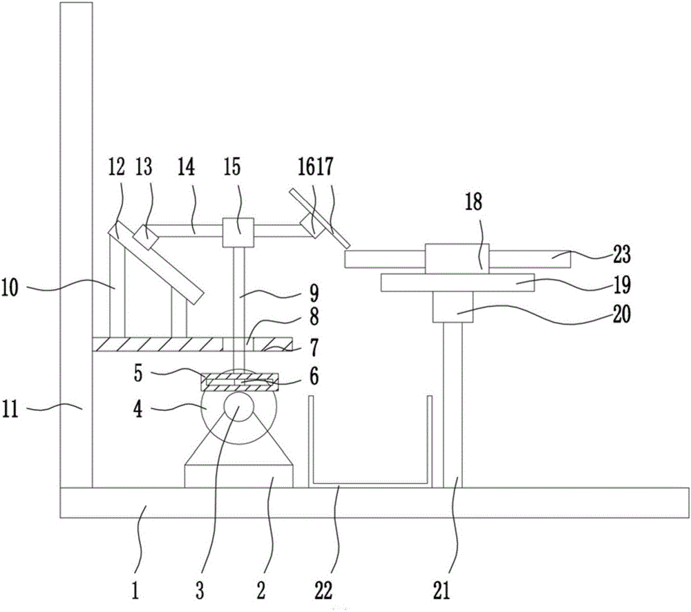
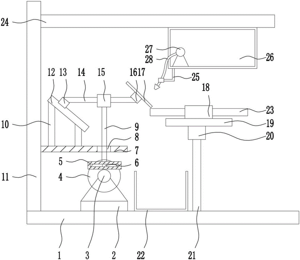
[0024] A steel pipe beveling device, such as Figure 1-4 As shown, it includes bottom plate 1, swing seat 2, motor Ⅰ 3, turntable 4, return slide rail 5, slider Ⅰ 6, guide plate 7, support rod Ⅰ 9, support rod Ⅱ 10, bracket 11, inclined slide rail 12, slider Ⅱ13, connecting rod 14, guide sleeve 15, motor Ⅱ16, cutting blade 17, clamping device 18, fixed plate 19, motor Ⅲ20, support rod Ⅲ21, collection frame 22, the top of bottom plate 1 is provided with bracket 11, from left to right in turn Swing seat 2, collecting frame 22 and support rod Ⅲ 21, the lower right part of the support 11 is provided with a guide plate 7, and the top of the guide plate 7 is provided with a support rod Ⅱ 10 symmetrically on the left side, and the top of the support rod Ⅱ 10 is provided with an inclined sliding rail 12, inclined sliding rail 12 is at a specific angle, the inclined slide rail 12 is slidably connected to a slider Ⅱ13, the right part of the slider Ⅱ13 is provided with a...


PUM


Abstract

The invention relates to an obliquely cutting device, in particular to a steel pipe obliquely cutting device. According to the technical problems to be solved, the steel pipe obliquely cutting device provided by the invention is simple in structure, convenient to operate and low in manufacturing cost. Through the steel pipe obliquely cutting device provided by the invention, the technical problems can be solved. The steel pipe obliquely cutting device provided by the invention comprises a bottom plate, a swinging seat, a motor I, a rotary disk, a concentric-square-shaped sliding rail, a sliding block I, a guide plate, a support rod I, support rods II, a support, an oblique sliding rail, a sliding block II, a connection rod, a guide sleeve, a motor II, a cutting piece, a clamping device, a fixed plate, a motor III, a support rod III and a collecting frame. The support, the swinging seat, the collecting frame and the support rod III are arranged at the top of the bottom plate sequentially from left to right. The guide plate is arranged on the lower portion of the right side of the support. The support rods II are arranged on the left side of the top of the guide plate symmetrically. The oblique sliding rail is arranged at the top ends of the support rods II and forms a specific angle. Through the steel pipe obliquely cutting device, the effects of a simple structure, convenient operation and low manufacturing cost are achieved.

Description

technical field [0001] The invention relates to a chamfering device, in particular to a steel pipe chamfering device. Background technique [0002] The development of steel pipe production technology began with the rise of the bicycle manufacturing industry, the development of petroleum in the early 19th century, the manufacture of ships, boilers, and aircraft during the two world wars, the manufacture of thermal power boilers after the Second World War, the development of the chemical industry and Drilling, production and transportation of oil and natural gas have strongly promoted the development of steel pipe industry in terms of variety, output and quality. The steel pipe is used to transfer fluid and powder, exchange heat and produce mechanical parts and containers, what's more it's a kind of economical steel. Using steel pipes to manufacture building structure grids, pillars and mechanical supports can reduce weight, save metal by 20-40%, and realize factory-like mech...

Claims


Application Information

Patent Timeline
IPC IPC(8): B23D21/02B23D33/00B23D45/12
CPCB23D21/02B23D33/00B23D45/12
Inventor 何建忠王振中庄国栋陈建林
Owner 嘉兴小出钢管有限公司
Why Eureka
Try Eureka