
Automatic wire feeding device on mechanical welding arm

A technology of mechanical welding and wire feeding device, which is applied in the direction of tin feeding device, welding equipment, metal processing equipment, etc., which can solve the problems of heavy physical injury of welding personnel, production efficiency and production volume that cannot meet the production demand, and improve welding efficiency effect

Active Publication Date: 2016-07-20
台州风达机器人科技有限公司
View PDF8 Cites 1 Cited by
  • Summary
  • Abstract
  • Description
  • Claims
  • Application Information

AI Technical Summary

Problems solved by technology

[0002] Welding is a manufacturing process and technology for joining metal or other thermoplastic materials such as plastics by means of heating, high temperature or high pressure. At present, the main fixed connection method between structural parts in the industrial industry, its welding can be divided into A variety of welding types, such as brazing with gas flame, the brazing realizes the connection by melting the welding wire through the flame, which is mainly used for the connection between pipe fittings. The brazing between existing pipe fittings generally uses manual brazing, and currently The production efficiency and production volume of manual brazing cannot meet the production needs, and manual brazing is also harmful to the welder's body. Therefore, robots are now introduced to realize automatic brazing, and robots need to be installed on the manipulator to achieve automatic brazing. wire feed fixture

Method used


Image

  • Automatic wire feeding device on mechanical welding arm
  • Automatic wire feeding device on mechanical welding arm
  • Automatic wire feeding device on mechanical welding arm

Examples


Embodiment Construction

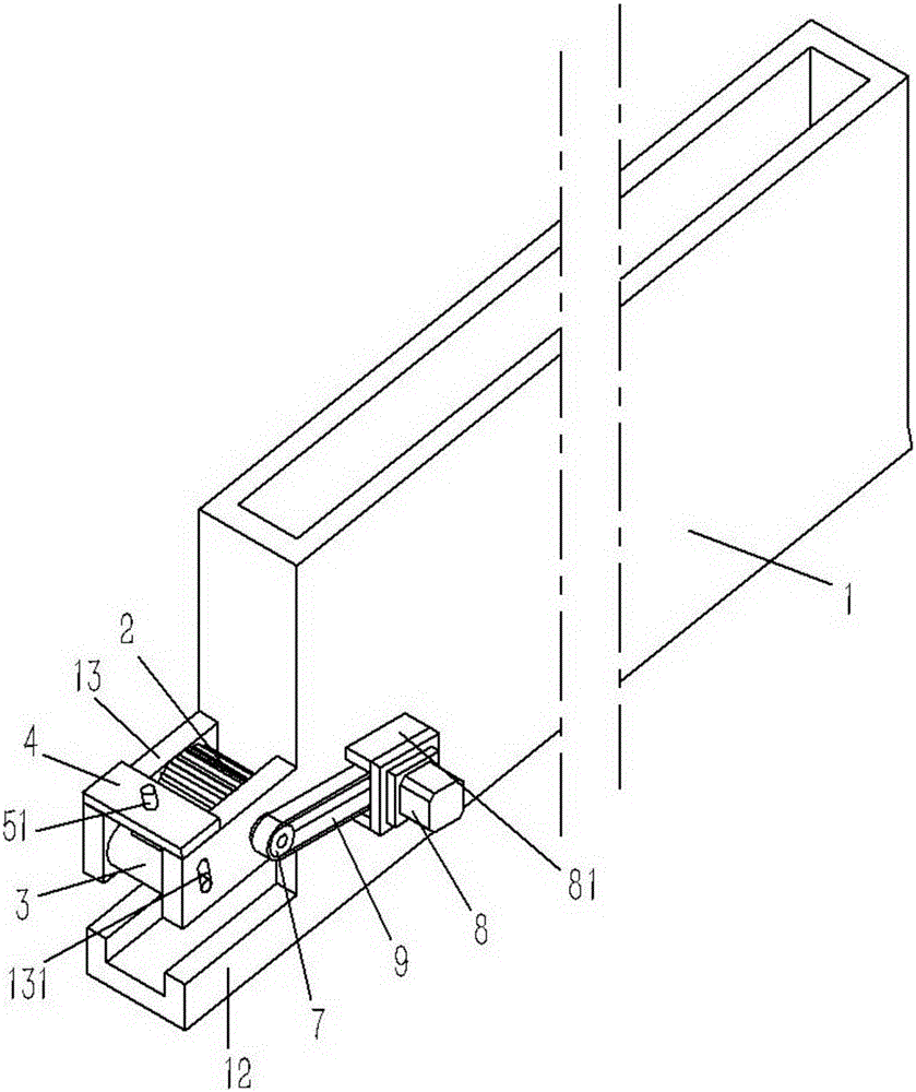
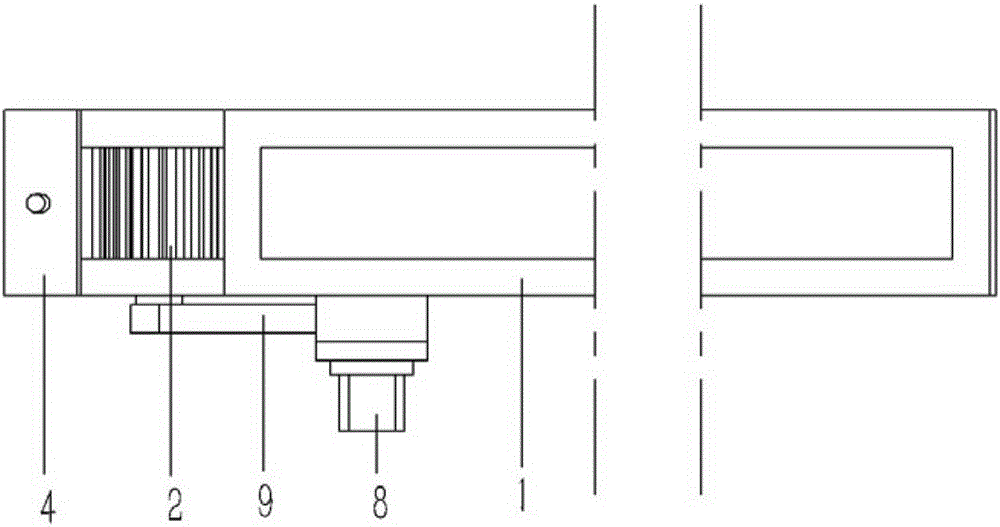
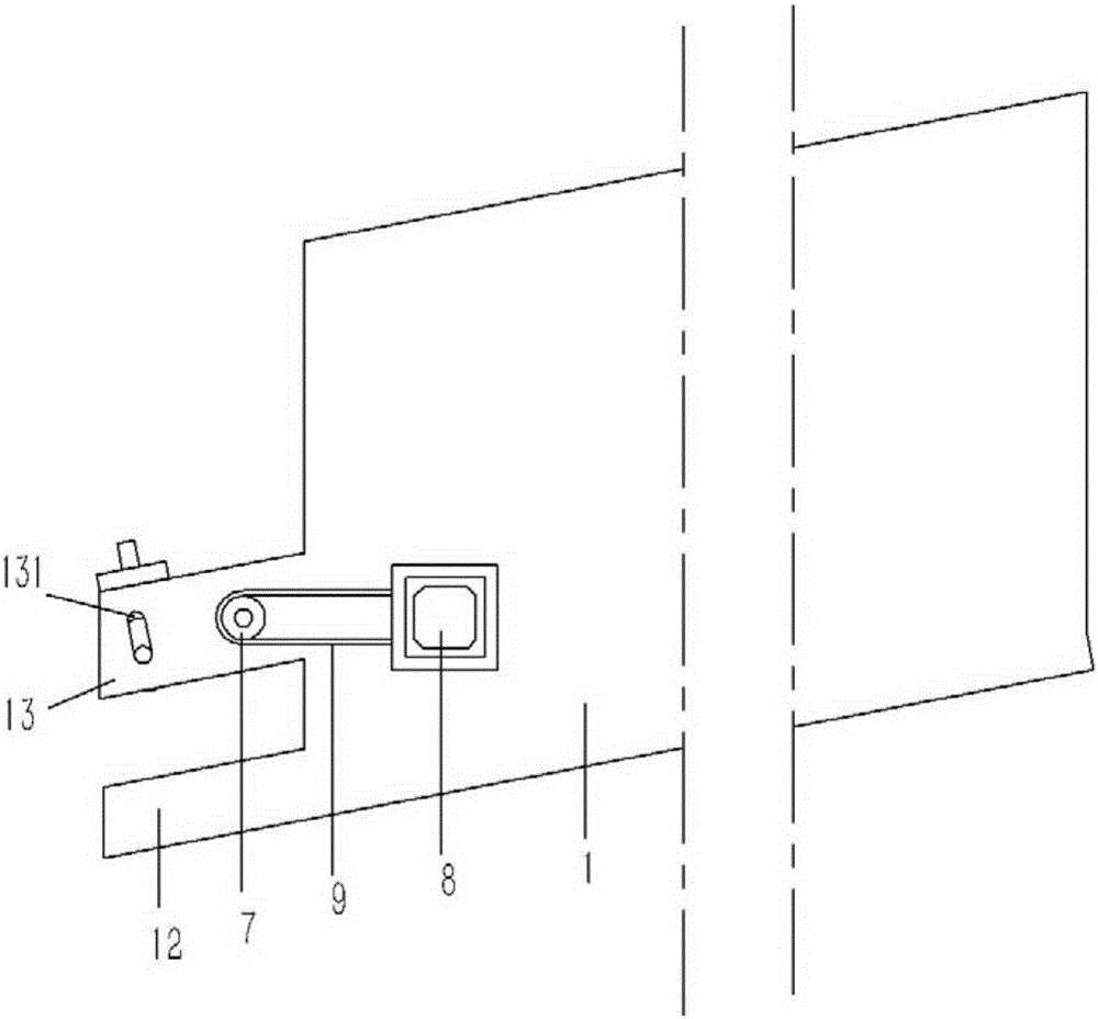
[0014] Example: see Figures 1 to 4 As shown, an automatic wire feeding device on a mechanical welding arm, including a flat wire feeding box 1, an inclined inner bottom surface is formed inside the wire feeding box 1, and the inner side of the lower end side of the inner bottom surface of the wire feeding box 1 is A wire feeding port 11 is formed on the wall, and an inclined wire feeding channel 12 is formed on the outer side of the wire feeding material box 1 outside the wire feeding port 11. A driving wheel 2 and a positioning wheel 3 are arranged above the wire feeding channel 12 to drive There are several triangular sawtooths 21 formed on the outer wall of the wheel 2, and the two ends of the mandrel of the driving wheel 2 are hinged on the lugs 13, and the lugs 13 are formed on the outer wall of the wire feeding box 1, and the lugs 13 are Formed with a waist-shaped hole 131, the two ends of the mandrel of the positioning wheel 3 are plugged in the waist-shaped hole 131 o...


PUM


Abstract

The invention discloses an automatic wire feeding device on a mechanical welding arm. Slot holes are molded in the bottom ends of the inner sides of the left side and the right side of a wire feeding material box of the automatic wire feeding device, a wire feeding nozzle communicated with the slot holes is molded on the outer wall of the left side of the wire feeding material box, and a guide groove equal with the slot holes in height is molded in the bottom end of the front end face of the wire feeding material box; a pulling block is inserted into the guide groove of the wire feeding material box, the front end of the pulling block extends out of the front end face of the wire feeding material box to be spirally connected to a lead screw, and the two ends of the lead screw are hinged to supports; the supports are fixed to the left side and the right side of the wire feeding material box, a wire feeding motor is fixedly connected to the support on the left side of the wire feeding material box, and a rotating shaft of the wire feeding motor and the lead screw are fixedly connected together; and a limiting mechanism is arranged at the position, above the lead screw, of the wire feeding material box. According to the automatic wire feeding device, as a jig for automatic wire feeding is designed for the mechanical arm of a robot, automatic brazing can be achieved by the robot, manual brazing can be replaced accordingly, and the welding efficiency is improved.

Description

Technical field: [0001] The invention relates to the technical field of robotic welding equipment, and more specifically relates to an automatic wire feeding device on a mechanical welding arm. Background technique: [0002] Welding is a manufacturing process and technology for joining metal or other thermoplastic materials such as plastics by means of heating, high temperature or high pressure. At present, the main fixed connection method between structural parts in the industrial industry, its welding can be divided into A variety of welding types, such as brazing with gas flame, the brazing realizes the connection by melting the welding wire through the flame, which is mainly used for the connection between pipe fittings. The brazing between existing pipe fittings generally uses manual brazing, and currently The production efficiency and production volume of manual brazing cannot meet the production needs, and manual brazing is also harmful to the welder's body. Therefore...

Claims


Application Information

Patent Timeline
IPC IPC(8): B23K3/06
CPCB23K3/063
Inventor 王文庆
Owner 台州风达机器人科技有限公司
Learn More