Forced return structure of the mold

A mold and return pin technology, which is applied in the field of forced return structure of the mold, can solve the problems of light load spring oblique pin return difficulty, large pin size, large withdrawal stroke and angle, etc.

Active Publication Date: 2017-12-26
MITAC PRECISION TECH(KUNSHAN) CORP
View PDF4 Cites 0 Cited by
  • Summary
  • Abstract
  • Description
  • Claims
  • Application Information

AI Technical Summary

Problems solved by technology

[0010] Therefore, the purpose of the present invention is to provide a forced return structure of the mold. When the forced return structure of the mold is poured into the hot runner to form the product, it can solve the problems caused by the large pin size, large withdrawal stroke and angle, and the use of heavy loads. The spring top does not move the oblique pin, and it is difficult to return the oblique pin with a light load spring

Method used


Image

  • Forced return structure of the mold
  • Forced return structure of the mold
  • Forced return structure of the mold

Examples


Embodiment Construction

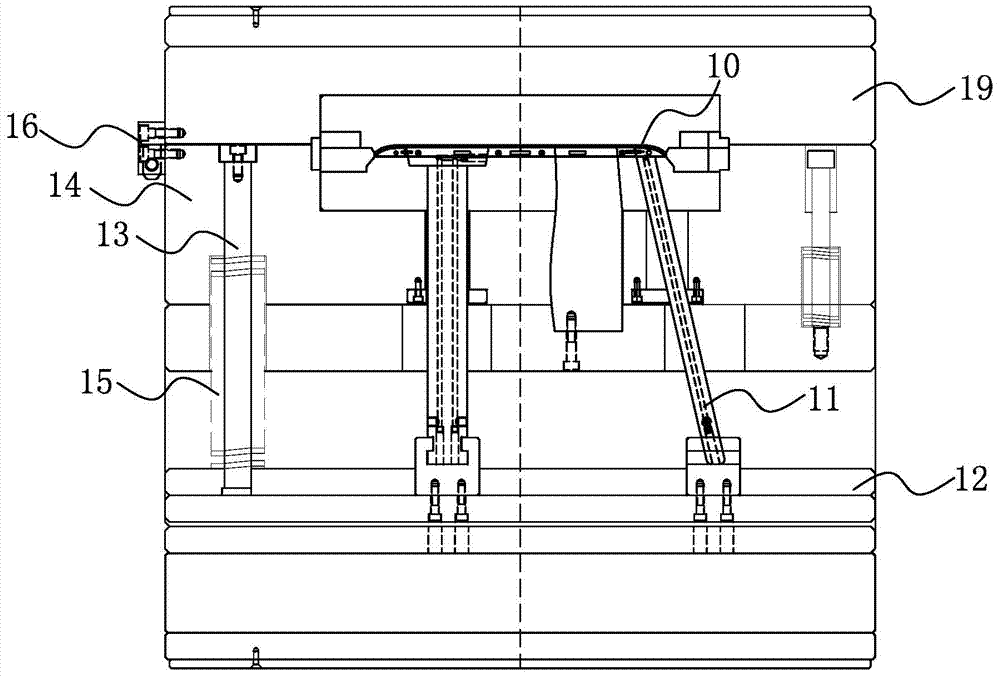
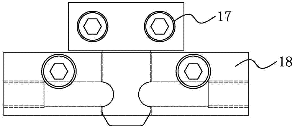
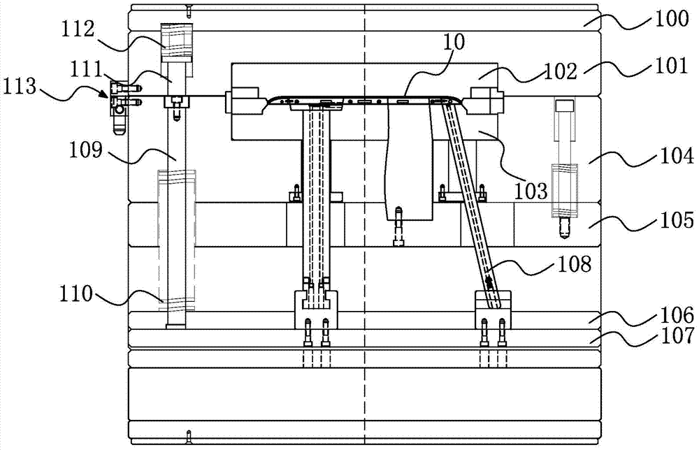
[0028] see image 3 and Figure 4 shown, where image 3 A schematic diagram illustrating the forced return structure of the mold of the present invention, Figure 4 A schematic diagram of the shutter in the forced return structure of the mold of the present invention is shown.

[0029] In this embodiment, the forced return structure of the mold of the present invention is used to pour the hot runner into the molded product, and the mold sequentially includes a lower fixing plate 100, a male template 101, a male mold core 102, a female mold core 103, Mother template 104, slider peeling plate 105, upper ejector plate 106 and lower ejector plate 107, the forced return structure of the mold includes:

[0030] Slanted pin 108, one end of which is located in the upper ejection plate 106, and the other end forms the product 10;

[0031] The first return pin 109, one end is fixed in the said mother template 104, and the other end is fixed in the said upper ejection plate 106;

[...


PUM


Abstract

A forced return structure for a mold, comprising: an oblique pin, one end of which is set in an upper ejector plate, and the other end to form a product; a first return pin, one end of which is fixed in a mother template, and the other end is fixed on the upper ejector plate middle; the first spring is sleeved on the outer edge of the first return pin, one end of the first spring is set in the female template, and the other end is against the upper ejector plate; the second return pin is set in the male template, the first There is a movable stroke between the second return pin and the male template. One end of the second return pin is against the first return pin; The other end; the shutter, which includes a locking seat and a locking sleeve, the locking seat is fixed on the male template, and the locking sleeve is fixed on the female template. The forced return structure of the mold of the present invention can solve the problem that when the hot runner is poured into the molding product, due to the large size of the inclined pin, the large withdrawal stroke and the angle, the heavy-load spring is used to top the fixed inclined pin, and the light-load spring inclined pin is used. Difficult questions to return to.

Description

【Technical field】 [0001] The invention relates to a mold structure, in particular to a forced return structure of the mold. 【Background technique】 [0002] In the production of products that require back pouring of hot runners, if there are barbs around the inside of the product, the product needs to be formed by the outer slider, the inner slider and the oblique pin. [0003] see figure 1 and figure 2 shown, where figure 1 It is a schematic diagram of the forced return structure of the mold in the prior art, figure 2 It is a schematic diagram of the shutter in the forced return structure of the mold in the prior art. The forced return structure of the existing mold is used to form the product 10 that needs to pour hot runner into the glue. The forced return structure of the mold includes: [0004] Slanted pin 11, one end of which is located in the upper ejection plate 12 of the mould, and the other end forms the product 10; [0005] Return pin 13, one end is fixed i...

Claims


Application Information

Patent Timeline
Patent Type & Authority Patents(China)
IPC IPC(8): B29C45/26B29C45/40B29C45/66
Inventor 郭明文
Owner MITAC PRECISION TECH(KUNSHAN) CORP
Why Eureka
Try Eureka