Flange hole vibration cleaning device

A technology for cleaning device and flange hole, which is applied in the field of flange hole vibration cleaning device, can solve the problems of iron slag not being blown out by wind and not being cleaned properly.

Inactive Publication Date: 2018-06-22
重庆市乐珐机电有限责任公司
View PDF1 Cites 6 Cited by
  • Summary
  • Abstract
  • Description
  • Claims
  • Application Information

AI Technical Summary

Problems solved by technology

[0004] But above-mentioned patent still has the following problem: only use blowpipe to blow off the residual iron filings and dirt in the hole of flange, when there is iron slag that does not fall off com...

Method used


Image

  • Flange hole vibration cleaning device
  • Flange hole vibration cleaning device

Examples


Embodiment Construction

[0020] The present invention will be described in further detail below by means of specific embodiments:

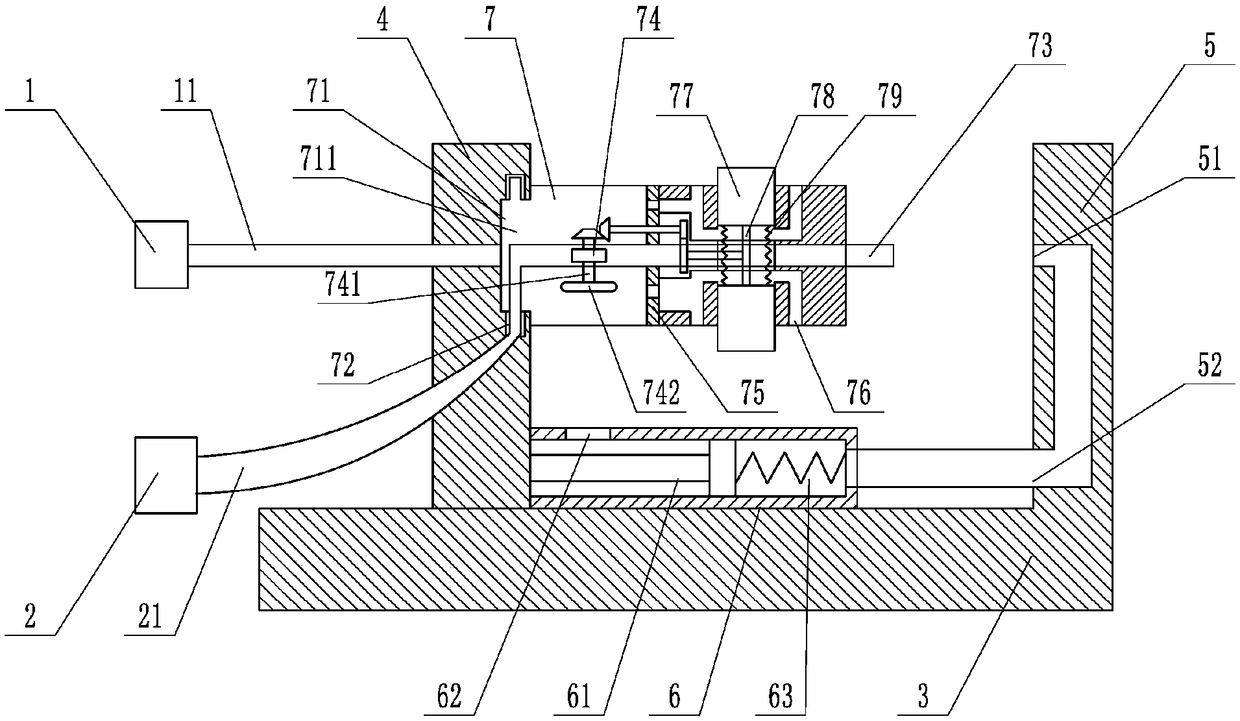
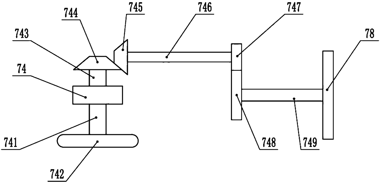
[0021] The reference signs in the drawings of the description include: motor 1, power rod 11, fan 2, air guide pipe 21, frame 3, fixed plate 4, connecting seat 5, first connecting hole 51, second connecting hole 52, piston Cylinder 6, piston rod 61, pressure relief port 62, first spring 63, hollow cleaning rod 7, connecting part 71, ventilation channel 711, fixing ring 72, blowing pipe 73, wind wheel 74, first connecting rod 741, negative pressure Blade 742, second connecting rod 743, first bevel gear 744, second bevel gear 745, first rotating rod 746, first gear 747, second gear 748, second rotating rod 749, filter screen 75, negative pressure hole 76, grinding block 77, cam 78, extension spring 79.

[0022] Such as figure 1 As shown, the flange hole vibration cleaning device includes a frame 3, a disc-shaped connecting seat 5 is welded on the right side of the frame 3...


PUM


Abstract

The invention belongs to the technical field of accessories of cleaning machines or equipment, and particularly relates to a flange hole vibration cleaning device. The flange hole vibration cleaning device comprises a rack, the rack is in sliding connection with a fixed disc, and a hollow cleaning rod is rotationally connected to the fixed disc. A blowing pipe is arranged in the hollow cleaning rod in a penetrating manner, the blowing pipe is connected with a fan, and an air wheel is rotationally connected in the blowing pipe. One side of the air wheel is coaxially connected with a negative pressure blade, and the other side of the air wheel is connected with a gear set. A negative pressure hole and an air flow one-way valve allowing the negative pressure blade to exhaust are formed in thehollow cleaning rod, and a gas channel communicating with the negative pressure hole is arranged in the cleaning rod. The hollow cleaning rod further comprises symmetrically arranged polishing blocks, and a cam is arranged between the two polishing blocks and driven by the gear set. By means of the scheme, a little scrap iron and dust adhering into a flange hole can be cleaned off, and the flangehole vibration cleaning device is usually used for cleaning machining of the flange hole.

Description

technical field [0001] The invention belongs to the technical field of accessories for cleaning machines or equipment, and in particular relates to a vibration cleaning device for flange holes. Background technique [0002] The flange is one of the important parts of the car. It not only has strict requirements on mechanical properties and dimensional accuracy, but also puts forward higher requirements on the overall cleanliness and particle size of the flange. So the cleanliness of the flange holes It is also the top priority. The current cleaning method is usually to use the air duct to align the holes to blow off the iron filings after processing. Since the number of holes in each flange is different, this method will inevitably have omissions, resulting in poor cleanliness. may have adverse consequences. [0003] For this reason, Chinese patent CN206588101U discloses a crankshaft flange screw hole chip blowing device, including a base, a blowing pipe, an air nozzle and...

Claims


Application Information

Patent Timeline
IPC IPC(8): B08B5/02B08B7/02
CPCB08B5/02B08B7/02
Inventor 印承霜
Owner 重庆市乐珐机电有限责任公司
Why Eureka
Try Eureka