
Automatic drying device

A drying device and automatic technology, which is applied in drying, drying machines, heating devices, etc., can solve the problems of artificial feeding and unloading, and achieve the effects of prolonging service life, reducing wear and tear, and reducing labor intensity

Active Publication Date: 2018-12-07
WENZHOU UNIVERSITY
View PDF7 Cites 8 Cited by
  • Summary
  • Abstract
  • Description
  • Claims
  • Application Information

AI Technical Summary

Problems solved by technology

[0004] The purpose of the present invention is to provide an automatic drying device to solve the problem of manual feeding and unloading in the process of drying materials

Method used


Image

  • Automatic drying device
  • Automatic drying device

Examples


Embodiment Construction

[0019] The following is further described in detail through specific implementation methods:

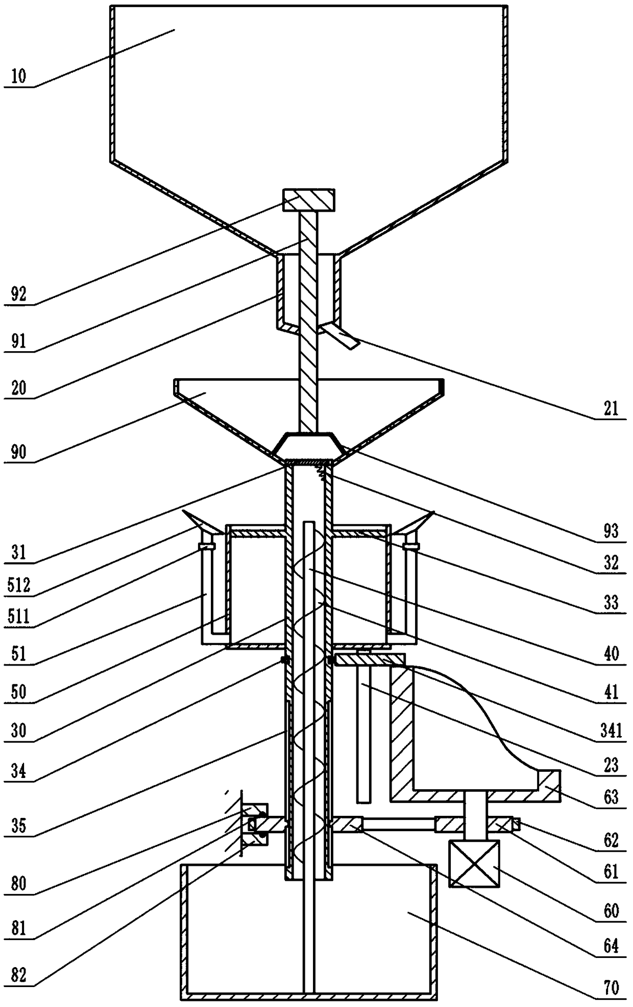
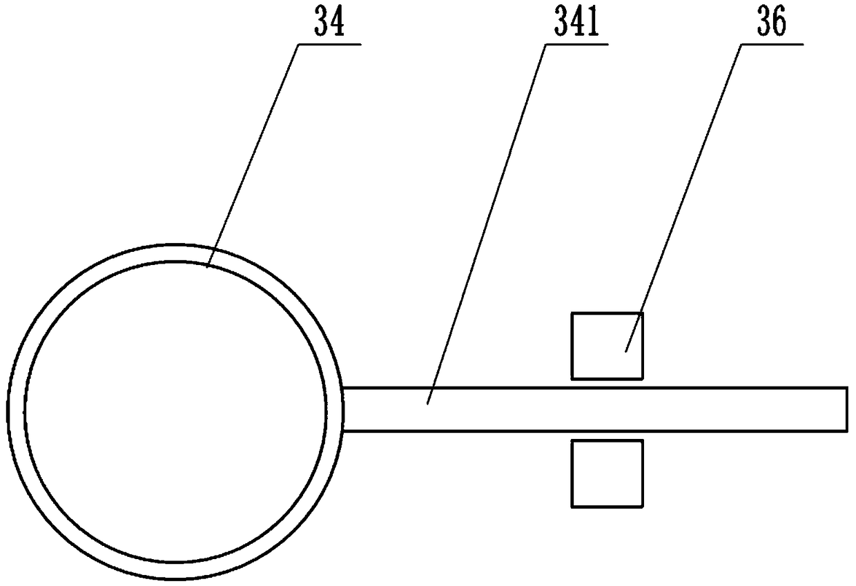
[0020] Instructions attached Figures 1 to 2 The reference signs in include: hopper 10, discharge pipe 20, output pipe 21, connecting column 30, material gate 31, spring 32, pressure plate 33, annular ring 34, connecting rod 341, chute 35, limit bar 36, Push rod 40, helical blade 41, piston barrel 50, exhaust pipe 51, one-way exhaust valve 511, jet nozzle 512, motor 60, first sprocket wheel 61, chain 62, cylindrical cam 63, second sprocket wheel 64, Collecting box 70, upper block 80, rolling ball 81, lower block 82, rotating disk 90, ejector bar 91, block 92, support 93.

[0021] Such as figure 1 As shown, the automatic drying device includes a rack, a drying unit, a power unit and a storage unit located above the drying unit. The storage unit includes a hopper 10 and a discharge pipe 20 communicating with the lower end of the hopper 10. The hopper 10 is used to place materials to...


PUM


Abstract

The invention belongs to the technical field of drying equipment, and particularly discloses an automatic drying device. The automatic drying device comprises a rack, a drying unit, a power unit and amaterial storing unit, wherein the material storing unit comprises a material hopper and a discharging pipe; the drying unit comprises a communication column and a rotating disc, a plurality of waterleakage holes are formed in the surface of the rotating disc, an ejection rod with the upper part positioned in the discharging pipe is fixed in the rotating disc, and a stop block is arranged on theejection rod; a material door is hinged to the upper end of the communication column, and an electric heating wire is arranged in the communication column; an annular groove is formed in the surfaceof the communication column, an annular ring is rotationally connected in the annular groove, and a connecting rod is arranged on the annular ring; limiting strips located on the two opposite sides ofthe connecting rod are fixed on the rack, and the power unit comprises a cylindrical cam, a motor for driving the cylindrical cam to rotate and a transmission mechanism used for driving the communication column to rotate; and one side surface of the connecting rod is in contact with the surface of a curve contour of the cylindrical cam. The device can solve the problem that manual feeding and discharging are needed in the process of drying materials.

Description

technical field [0001] The invention belongs to the technical field of drying equipment, in particular to an automatic drying device. Background technique [0002] A drying device refers to a combination of a series of mechanical equipment that dries moisture or other liquids on the surface of an object through certain technical means. At present, the commonly used drying devices include belt drying, drum drying, box drying, tower drying and other modes. radiation etc. [0003] After cleaning waste sand, waste plastics and other materials, these materials are usually dried to facilitate the next processing procedure. Although the existing drying device can dry the materials well, the workers need to personally operate the materials into the drying device and send the materials away after drying, which is inefficient and labor-intensive. . Contents of the invention [0004] The object of the present invention is to provide an automatic drying device to solve the problem...

Claims


Application Information

Patent Timeline
IPC IPC(8): F26B5/08F26B17/22F26B23/06F26B25/04
CPCF26B5/08F26B17/22F26B23/06F26B25/04
Inventor 谢小文
Owner WENZHOU UNIVERSITY
Learn More