A full hydraulic drive road sweeper walking high and low speed switching device

A high-low speed, road sweeper technology, applied in the direction of control devices, transportation and packaging, vehicle parts, etc., can solve the problems of small driving speed, narrow speed regulation range, unfavorable control, etc., and achieve fast transition speed and speed regulation range Big, Slow Effects

Active Publication Date: 2017-11-28
XUZHOU XUGONG ENVIRONMENTAL TECH CO LTD
View PDF6 Cites 0 Cited by
  • Summary
  • Abstract
  • Description
  • Claims
  • Application Information

AI Technical Summary

Problems solved by technology

The walking mode of this road sweeper has the following disadvantages: the range of speed regulation is narrow, the driving speed can only be adjusted by the engine speed and the displacement of the main pump, and there is no high and low speed gear adjustment
During the operation, in order to achieve a better working effect, the driving speed needs to be controlled at a lower driving speed and a higher engine speed, which requires the operator to pull the hand accelerator to a larger position to increase the engine speed, and at the same time lightly step on the The pedal is used to maintain a small driving speed. In this mode of operation, the operation of maintaining a low driving speed by lightly stepping on the pedal is not conducive to the operator's control of the sweeping operation.

Method used


Image

  • A full hydraulic drive road sweeper walking high and low speed switching device
  • A full hydraulic drive road sweeper walking high and low speed switching device
  • A full hydraulic drive road sweeper walking high and low speed switching device

Examples


Embodiment Construction

[0018] Below in conjunction with accompanying drawing of description, the present invention will be further described.

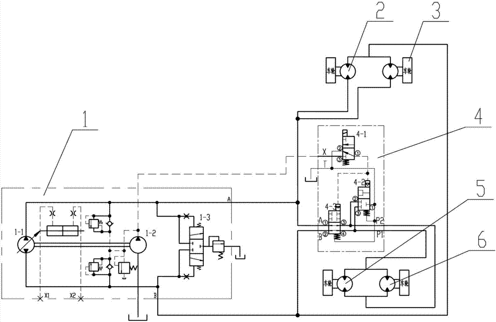
[0019] like image 3 The high-low speed switching device of a fully hydraulically driven road sweeper shown includes a closed pump 1 connected to the hydraulic oil tank and a high-low speed switching valve 4 connected to the A port of the closed pump 1; the closed pump 1 Port A of the left front wheel motor 2 and the oil inlet of the right front wheel motor 3 are respectively connected, and the oil outlet of the left front wheel motor 2 and the oil outlet of the right front wheel motor 3 are connected with the closed pump 1 connected to port B; the P1 port of the high and low speed switching valve 4 is connected to the oil inlet of the left rear wheel motor 5 and the oil inlet of the right rear wheel motor 6 respectively, and the P2 port of the high and low speed switching valve 4 is connected to the left The oil outlet of rear wheel motor 5 is connected wi...


PUM


Abstract

The invention discloses a walking high-low-speed switching device of a fully hydraulic driving road sweeping machine. The walking high-low-speed switching device comprises a closed pump and a high-low-speed switching valve, wherein the closed pump is connected with a hydraulic oil tank; the high-low-speed switching valve is connected with an opening A of the closed pump; the closed pump comprises a plunger piston pump connected with an oil supplementing pump and a flushing valve; the high-low-speed switching valve comprises a two-position three-way electromagnetic reversing valve, a two-position three-way liquid control reversing valve and a two-position four-way liquid control reversing valve. Through the two-drive and four-drive switching, the high-low-speed switching of the running speed can be realized; the four-wheel driving is used in the road sweeping mode, and the speed is low; the two-front-wheel driving is used in the transfer mode, and the transfer speed is high; the high-low-speed switching of the four-wheel driving road sweeping machine is realized; the speed regulation can be performed through engine rotating speed, main pump discharging capacity and high-low-speed switching; the speed regulating range is large. The tire abrasion phenomenon due to different inner and outer wheel rotating speeds during the steering caused by vehicle frame structure does not exist in any mode; meanwhile, the walking high-low-speed switching device is applicable to a road sweeping machine with an integral underpan.

Description

technical field [0001] The invention relates to a road sweeper hydraulic system, in particular to a fully hydraulically driven road sweeper walking high and low speed switching device, which belongs to the technical field of road sweeper walking control hydraulic systems. Background technique [0002] At present, the cleaning of streets, parks, squares, and sidewalks in most domestic cities is generally dominated by manual cleaning; with the development of cities and the increase in labor costs, this traditional manual cleaning method is increasingly being replaced by cleaning mechanization. Tall sweepers instead. The existing small full-hydraulic drive road sweepers are not only compact in structure, simple in operation, and high in cleaning efficiency, but also generally use closed hydrostatic walking hydraulic systems, which are driven by hydraulic motors installed on tires; and four-wheel drive Due to its large driving force, the road sweeper is more and more widely use...

Claims


Application Information

Patent Timeline
Patent Type & Authority Patents(China)
IPC IPC(8): B60K17/356B60K23/08
CPCB60K17/356B60K23/08
Inventor 程磊单龙郭兵贾文斌谌俊杰王斌王金东
Owner XUZHOU XUGONG ENVIRONMENTAL TECH CO LTD
Why Eureka
Try Eureka