DC brushless coreless motor

A DC brushless, hollow cup technology, applied in the shape/style/structure of electrical components, electromechanical devices, winding conductors, etc., can solve problems such as brush wear and tear, and achieve the effects of long life, low heat generation, and low cost

Inactive Publication Date: 2018-09-04
杭州园心自动化科技有限公司
View PDF4 Cites 0 Cited by
  • Summary
  • Abstract
  • Description
  • Claims
  • Application Information

AI Technical Summary

Problems solved by technology

Brushed motors need to use sliding contact due to the transmission of electricity. The commutator and brushes will be worn out due to friction, resulting in problems such as life.

Method used


Image

  • DC brushless coreless motor
  • DC brushless coreless motor
  • DC brushless coreless motor

Examples


Embodiment 1

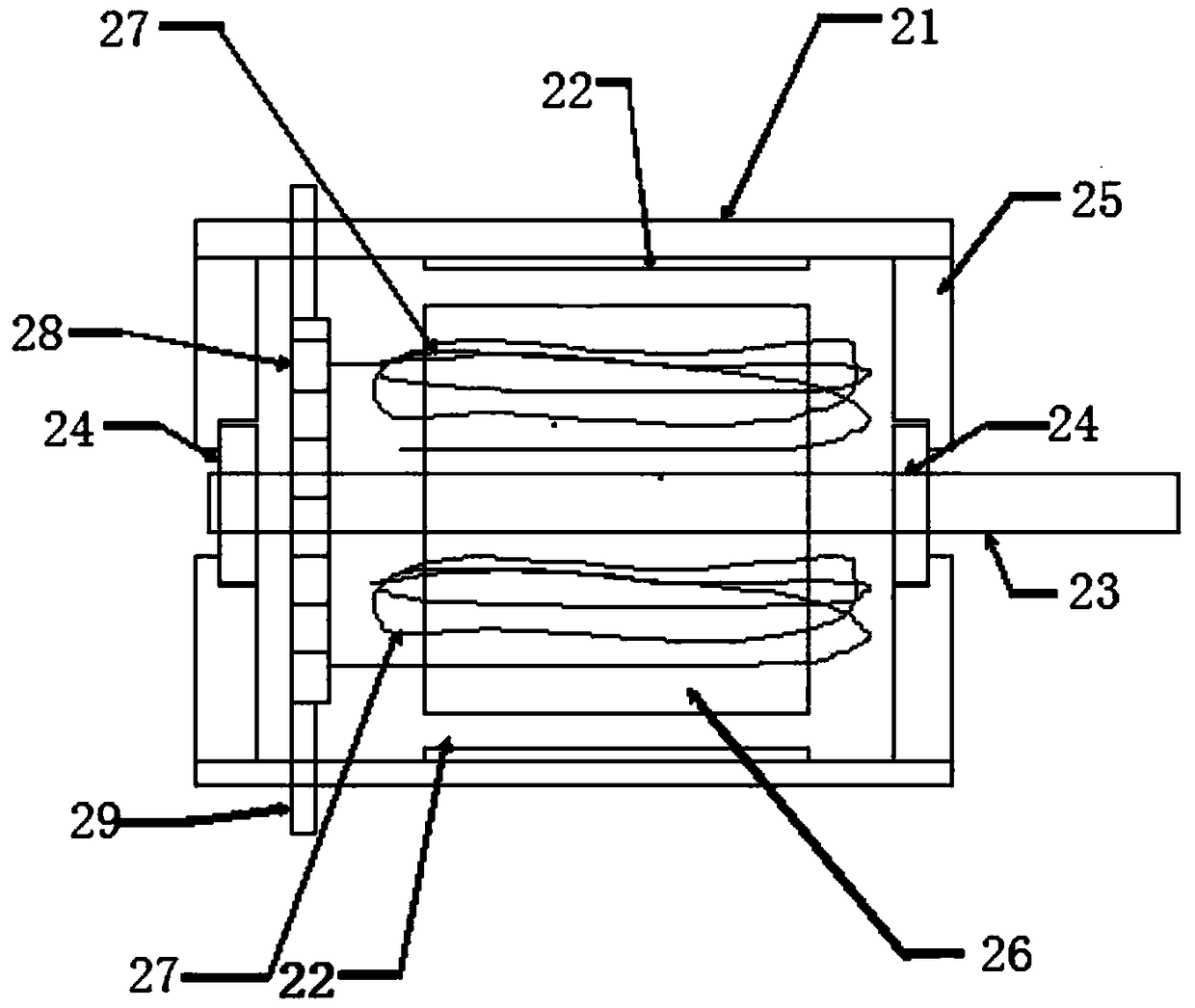
[0023] Such as Figure 4 As shown, a DC brushless coreless motor includes a rotor 2 with magnets, several groups of coils 3, end covers 6, casing 1, and bearings 4, and the rotor 2 with magnets is provided with a rotating shaft 13, so The bearing 4 is sleeved on the rotating shaft 13, the rotating shaft 13 is installed on the casing 1, the casing 1 is connected with the end cover 6, and the several groups of coils 3 are directly fixed on the inner wall of the casing 1. The bearings 4 are located on both sides of the rotating shaft 13 . The casing 1 is insulated from several groups of coils 3 . There are 14 groups of coils 3, all of which are air core coils.

Embodiment 2

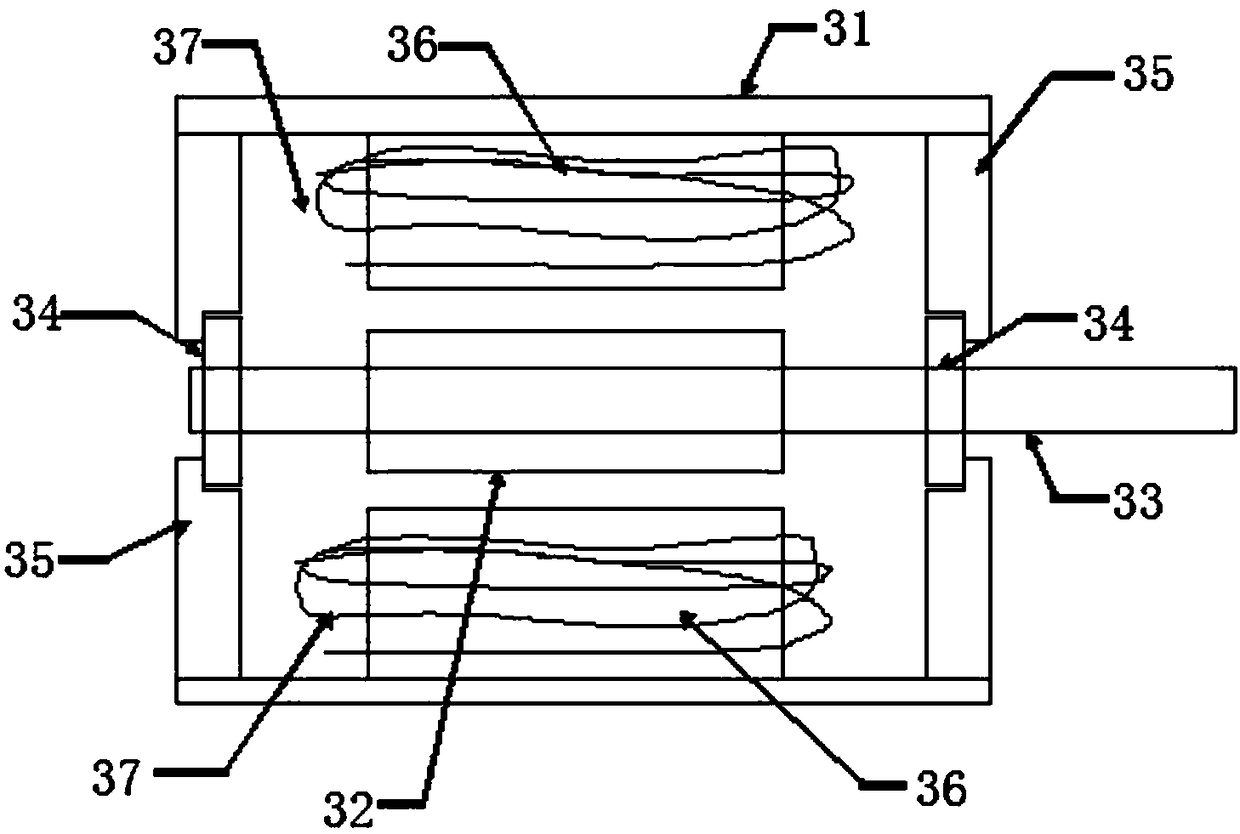
[0025] Such as Figure 5 As shown, a DC brushless coreless motor includes a rotor 2 with magnets, several groups of coils 3, end covers 6, a casing 1, bearings 4, and a rotating shaft 13, and the rotor 2 with magnets is provided with a rotating shaft 13. The bearing 4 is set on the rotating shaft 13, the rotating shaft 13 is installed on the casing 1, the casing 1 is connected with the end cover 6, and the several groups of coils 3 are fixed on the inner wall of the casing 1 through the bracket 7 superior. The bearings 4 are located on both sides of the rotating shaft 13 . The support 7 is insulated from several sets of coils 3 . The coils 3 are all air core coils.

Embodiment 3

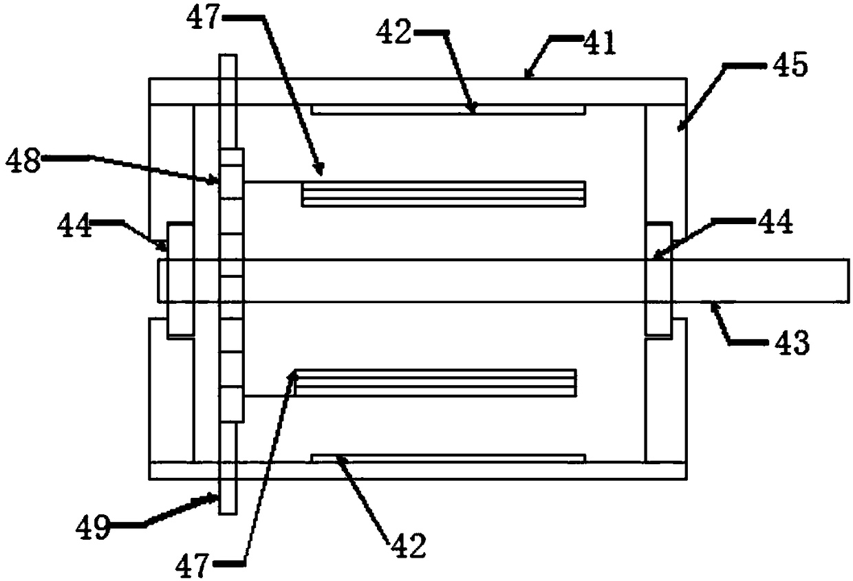
[0027] Such as Figure 6 As shown, a DC brushless coreless motor includes a rotor 2 with magnets, several groups of coils 3, end covers 6, a casing 1, bearings 4, and a rotating shaft 13, and the rotor 2 with magnets is provided with a rotating shaft 13. The bearing 4 is set on the rotating shaft 13, the rotating shaft 13 is installed on the casing 1, the casing 1 is connected with the end cover 6, and the several groups of coils 3 are directly fixed on the end cover 6. The bearing 4 is located on one side of the rotating shaft 13 . The coils 3 are all air core coils. The end cap 6 is insulated from several sets of coils 3 .

[0028] The power supply of the present invention is directly connected to the coil without wear and tear, so the service life is long, and the present invention has the advantages of fast start-up and low heat generation, simple structure and low cost.


PUM


Abstract

The invention discloses a DC brushless coreless motor, which comprises a rotor with a magnet, a plurality of groups of coils, an end cover, a housing and a bearing. The rotor with the magnet is provided with a rotating shaft; the bearing is sleeved on the rotating shaft; the rotating shaft is arranged on the housing; the housing is connected with the end cover; and the plurality of groups of coilsare directly fixed to the inner wall of the housing or are fixed to the inner wall of the housing through a support or are directly fixed to the end cover. A power supply is directly connected with the coils, and wear phenomenon does not exist, so that the service life is long; the DC brushless coreless motor has the advantages of fast start and small heating; and the DC brushless coreless motoris simple in structure and low in cost.

Description

technical field [0001] The invention relates to a DC brushless hollow cup motor. Background technique [0002] The main components of the motor are the stator and the rotor. The so-called stator is fixed and does not rotate when it works, and the so-called rotor rotates when it works. There are two types of DC motors, brushed and brushless. [0003] Brushed DC motors such as figure 1 As shown, 21: casing, 22: stator magnet, 23: shaft, 24: bearing, 25: end cover, 26: rotor core, 27: winding coil, 28: commutator, 29: brush, with brush The DC motor stator has magnets, and the coil is wound on the rotor core. The rotor rotates during operation. In order to connect the coil on the rotor to the external power supply, the brushed DC motor must have a commutator, and the commutator is in sliding contact with the brushes fixed on the casing, so as to achieve the purpose of power supply. Brushed motors need to use sliding contact due to the transmission of electricity, and the co...

Claims


Application Information

Patent Timeline
Patent Type & Authority Applications(China)
IPC IPC(8): H02K29/00H02K3/04
CPCH02K3/04H02K29/00
Inventor 侯春洪
Owner 杭州园心自动化科技有限公司
Why Eureka
Try Eureka