Chopped fiber dispersion machine

A technology of chopped fiber and dispersing machine, which is applied in the direction of mixing method, glass manufacturing equipment, solid and solid mixing, etc., which can solve the problems that the original shape and dispersion effect of the fiber cannot be guaranteed, and achieve small wear and good fiber dispersibility Effect

Inactive Publication Date: 2020-11-20
陕西华特新材料股份有限公司
View PDF4 Cites 1 Cited by
  • Summary
  • Abstract
  • Description
  • Claims
  • Application Information

AI Technical Summary

Problems solved by technology

[0004] In order to overcome the problems existing in the prior art that the original shape and dispersion effect of the fiber cannot be guaranteed, the present invention proposes a chopped fiber disperser

Method used


Image

  • Chopped fiber dispersion machine
  • Chopped fiber dispersion machine
  • Chopped fiber dispersion machine

Examples


Embodiment Construction

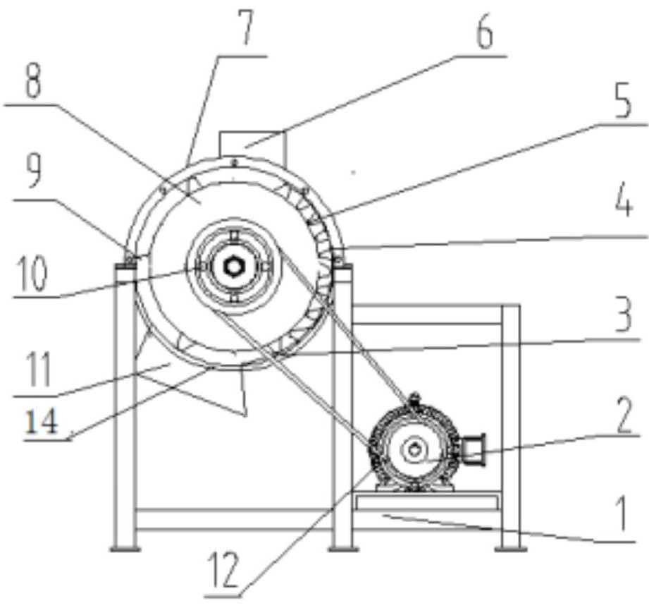
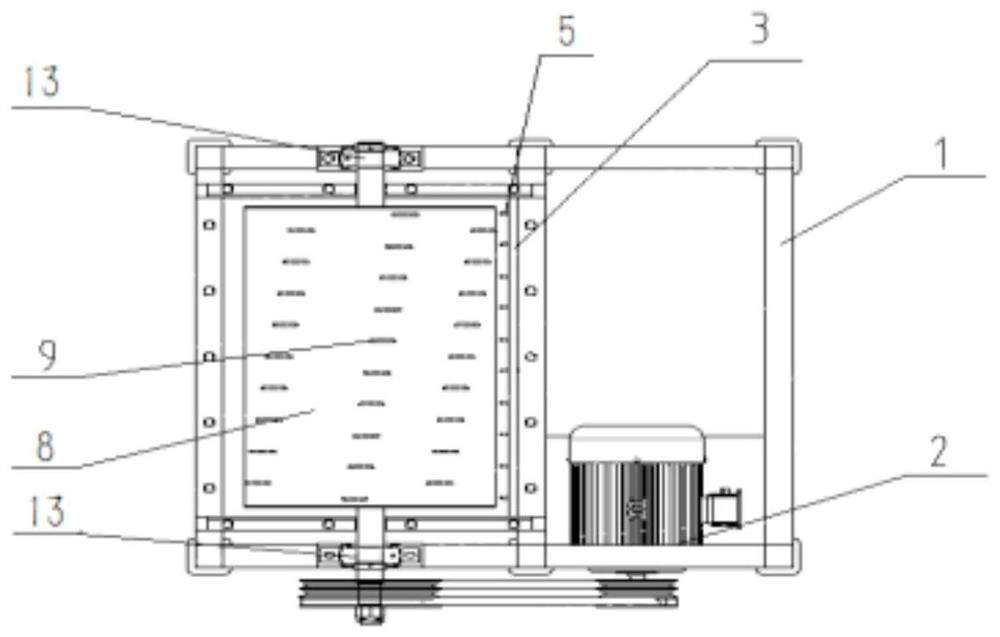
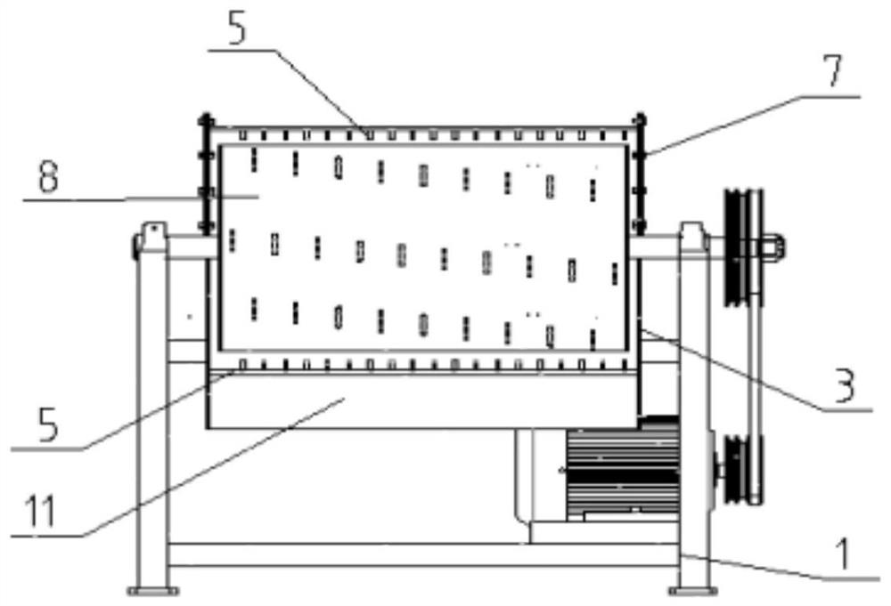
[0025] This embodiment is a glass fiber dispersing machine, including a frame 1, a motor 2, a lower casing 3, a dispersing tooth plate 4, a tooth plate dispersing tooth 5, a feeding port 6, an upper casing 7, a rotating inner cylinder 8, Dispersing teeth 9, large pulley 10, discharge port 11, small pulley 12, bearing seat 13 and lower casing 14 in the inner cylinder. in:

[0026] The semicircular upper casing 7 is fixed on the upper end surface of the frame; the rotating inner cylinder 8 is located below the semicircular upper casing 7, and the two ends of the rotating inner cylinder rotating shaft are installed on the rotating shaft through the bearing seat 12. on the crossbeam of the frame 1; the lower casing 14 is located below the rotating inner tube 8 and fixed between the poles of the frame; the upper casing, the lower casing 14 and the rotating inner The barrels are coaxial, and a circle with the same inner diameter is formed by the upper shell and the lower shell, for...


PUM

PropertyMeasurementUnit
diameteraaaaaaaaaa

Abstract

The invention discloses a chopped fiber dispersion machine, which is characterized in that toothed plate dispersion teeth positioned on the inner circumferential surface of a protective shell and inner barrel dispersion teeth positioned on the outer circumferential surface of a rotary inner barrel are arranged in a staggered manner; a motor drives the rotary inner barrel to rotate; chopped yarns are fed into a material inlet; the chopped yarns are dispersed at the material inlet by utilizing the mutual impact effect of high rotating speeds of the dispersing teeth; and when the chopped yarns are dragged into the barrel body and slide relative to the surfaces of the dispersing teeth of the adjacent inner barrel and outer barrel, the chopped yarns are separated and discharged along with airflow generated by high-speed rotation of the inner barrel, so that finally the purpose of dispersing fibers is achieved. According to the invention, blocky fibers can be dispersed into fibers with the diameter of 1 mm or below, the dispersion rate can reach 95% or above, the dispersion rate of the fibers with the diameter of 3 mm or below can reach 99%, abrasion of dispersion equipment to the fibersis very small, the phenomenon that the surfaces of the fibers are abraded and fuzzed is basically avoided, and the fiber dispersity is good.

Description

technical field [0001] The invention relates to the field of chopped fiber preparation, in particular to a chopped fiber disperser. Background technique [0002] Glass fiber acid leaching is an important and indispensable process for the production of glass fiber chopped strand products. It is to precipitate the phase-separated non-siliceous phase in the glass fiber structure under the action of acid to make the SiO2 content in the structure Reach above 96%. Because the glass fiber presents a compact block structure ranging from 60mm to 80mm after wire drawing and chopping, especially at the knife edge position at both ends, after high-speed cutting by the knife, the yarn and yarn are bonded together due to the presence of the sizing agent. Difficult to disperse. During the reaction process of glass fiber and acid leaching, the outer fiber first reacts with the acid solution, which causes the alkaline product produced by the chopped strand reaction to be enriched in a larg...

Claims


Application Information

Patent Timeline
Patent Type & Authority Applications(China)
IPC IPC(8): B01F3/18C03B37/10
CPCC03B37/10B01F23/60
Inventor 武晓春许联盟陈志辉
Owner 陕西华特新材料股份有限公司
Why Eureka
Try Eureka