Cooling device of food transportation equipment

A technology of transportation equipment and cooling device, which is applied in the field of machinery, can solve the problems of cumbersome operation, slow cooling speed of natural cooling method, and affecting food processing efficiency, so as to save cooling time, ensure stability, and improve food cooling efficiency.

Active Publication Date: 2016-07-20
湖北施州实业有限公司
View PDF4 Cites 10 Cited by
  • Summary
  • Abstract
  • Description
  • Claims
  • Application Information

AI Technical Summary

Problems solved by technology

The existing cooling method is to use natural cooling or special cooling equipment for cooling. The cooling speed of natural cooling method is slow, which affects the processing efficiency of food; if spe

Method used


Image

  • Cooling device of food transportation equipment
  • Cooling device of food transportation equipment
  • Cooling device of food transportation equipment

Examples


Embodiment 1

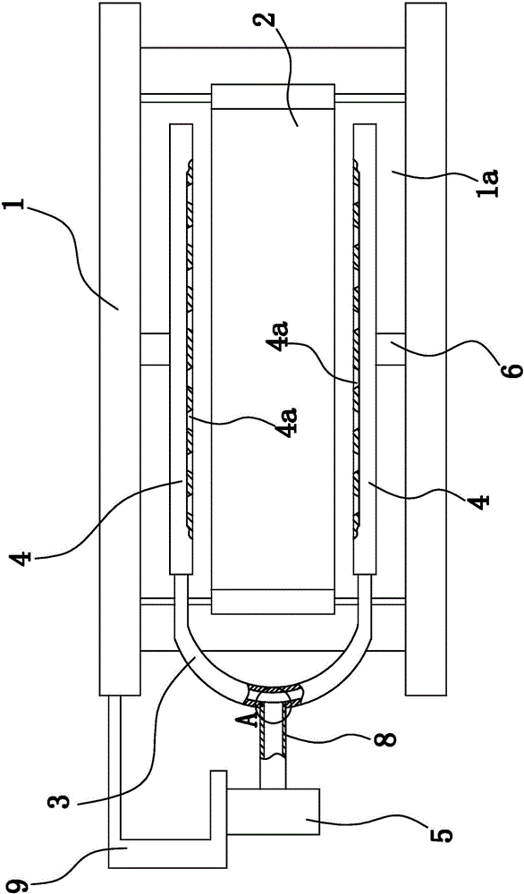
[0024] Such as figure 1 As shown, the food transportation equipment includes a support 1 with a conveying channel 1a, and a conveyor belt 2 is arranged in the conveying channel 1a, and the conveyor belt 2 is arranged along a horizontal direction. The cooling device of the food transportation equipment is composed of an air inlet pipe 3, an air outlet pipe 4, a blower fan 5 and the like.

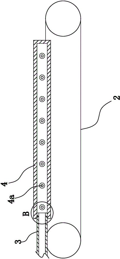
[0025] Wherein, there are two outlet pipes 4 and each outlet pipe 4 is straight. Each air outlet pipe 4 is fixed in the conveying channel 1a, and the two air outlet pipes 4 are located on both sides of the conveyer belt 2 respectively. Such as figure 1 As shown, the distribution direction of the two air outlet pipes 4 is perpendicular to the conveying direction of the conveyor belt 2 , and the axial extension direction of the air outlet pipes 4 is consistent with the conveying direction of the conveyor belt 2 . In this embodiment, the air outlet tube 4 is fixed to the bracket 1 throu...

Embodiment 2

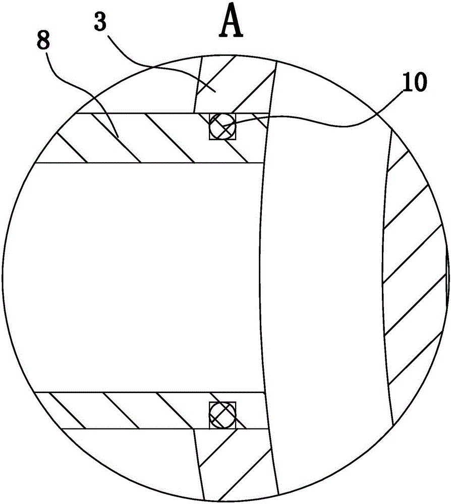
[0030] The structure and principle of this second embodiment are basically the same as that of the first embodiment, except that the outer walls of both ends of the intake pipe 3 have ring-shaped sealing parts, and the end faces of the two sealing parts are respectively connected to the corresponding openings. The end faces meet. An annular sealing groove is provided on the end surface of the sealing part, and an annular sealing gasket is arranged in the sealing groove, and the two end surfaces of the annular sealing gasket respectively abut against the bottom wall of the sealing groove and the end surface of the opening end.


PUM


Abstract

The invention provides a cooling device of food transportation equipment and belongs to the technical field of machinery.The cooling device solves the problem that existing food transportation equipment affects food processing efficiency.The food transportation equipment comprises a support with a conveying channel, and a conveyor belt is arranged in the conveying channel.The cooling device comprises two air outlet pipes fixed into the conveying channel, the two air outlet pipes are located on the two sides of the conveyor belt respectively, the distribution directions of the two air outlet pipes are perpendicular to the conveying direction of the conveyor belt, the two right opposite sides of the two air outlet pipes are provided with air outlet holes, each air outlet pipe is provided with the multiple air outlet holes, and the air outlet holes in one air outlet pipe are opposite to the air outlet holes in the other air outlet pipe in a one-to-one mode.The conveying channel is internally provided with a U-shaped air inlet pipe, the two ends of the air inlet pipe are tubular and inserted into and fixed into two open ends in a sealing mode, and an air feeder communicated with an inner cavity of the air inlet pipe is fixed to the support.The cooling device of the food transportation equipment has the advantage of being capable of improving the food processing efficiency.

Description

technical field [0001] The invention belongs to the technical field of machinery, and relates to food transportation equipment, in particular to a cooling device for food transportation equipment. Background technique [0002] At present, in the process of food processing, most of them require high-temperature treatment. After the food is subjected to high-temperature treatment, the processed food needs to be cooled before being transported for the next step. The existing cooling method is to use natural cooling or special cooling equipment for cooling. The cooling speed of natural cooling method is slow, which affects the processing efficiency of food; if special cooling equipment is used for cooling, the food needs to be taken to the place where the equipment is placed for cooling. It is more cumbersome and will also affect the processing efficiency of food. Contents of the invention [0003] The purpose of the present invention is to solve the above-mentioned prob...

Claims


Application Information

Patent Timeline
IPC IPC(8): B65G15/22B65G49/00
CPCB65G15/22B65G49/00B65G2201/0202
Inventor 宋晓玲
Owner 湖北施州实业有限公司
Why Eureka
Try Eureka