Integral floating driving device for belt conveyor power coiling block

A technology of driving device and belt conveyor, which is applied in the direction of conveyor, transportation and packaging, etc. It can solve the problems affecting the normal operation of the belt conveyor and accelerating the damage of the drum gear coupling, so as to facilitate observation and maintenance and prolong the service life , reliable effect

Inactive Publication Date: 2016-07-20
NANJING HIGH SPEED & ACCURATE GEAR GRP
View PDF7 Cites 1 Cited by
  • Summary
  • Abstract
  • Description
  • Claims
  • Application Information

AI Technical Summary

Problems solved by technology

[0003] The purpose of the present invention is: for the current reducer and the belt conveyor are respectively rigidly positioned on different bases, a relatively large radial shear force is formed on the drum-shaped gear coupling at the junction of the two shafts during work, and the drum-shaped gear is accelerated. The damage of the tooth coupling, a practical problem that affects the normal operation of the belt conveyor, provides a new integral floating drive device for the power drum of the belt conveyor

Method used


Image

  • Integral floating driving device for belt conveyor power coiling block
  • Integral floating driving device for belt conveyor power coiling block
  • Integral floating driving device for belt conveyor power coiling block

Examples


Embodiment Construction

[0015] The accompanying drawings disclose the specific structures of the embodiments of the present invention without limitation, and the present invention will be further described below in conjunction with the accompanying drawings.

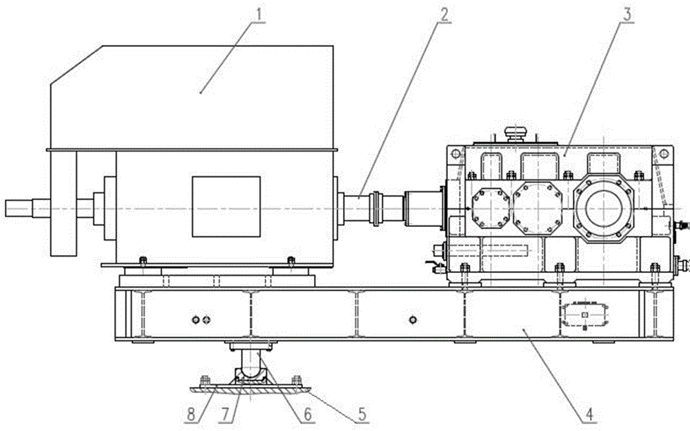
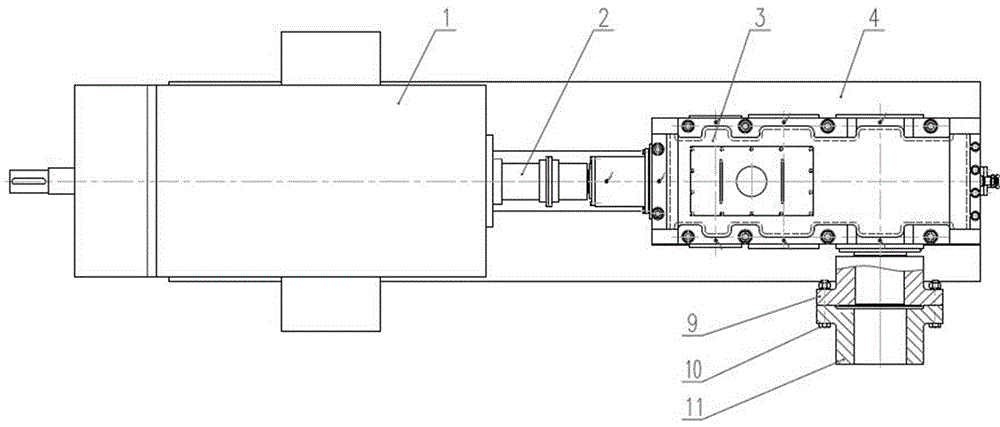
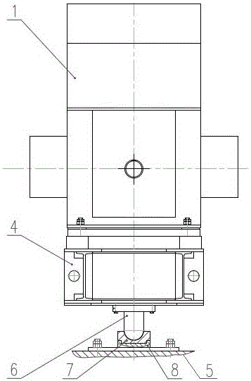
[0016] Depend on Figure 1-3 It can be seen that the present invention includes a motor 1, a shaft coupling and a speed reducer 3, the central axis of the input shaft and the output shaft of the speed reducer 3 are orthogonal, the motor 1 and the speed reducer 3 are fixedly mounted on a floating base 4, and the floating base 4 and the There is a floating support between the foundations 5, the output end of the motor 1 is connected with the input end of the reducer 3 through the drum gear coupling 2, and the output end of the reducer 3 is connected with the power reel of the belt drive through a rigid coupling .

[0017] In this embodiment, the floating support is arranged on the floating base 4 below the motor 1 (such as figure 1 ), and locat...


PUM


Abstract

The invention relates to an integral floating driving device for a belt conveyor power coiling block. The integral floating driving device comprises a motor, couplers and a reduction gear, and is characterized in that the central axes of the input shaft and the output shaft of the reduction gear are orthogonal to each other; the motor and the reduction gear are fixedly arranged on a floating base; a floating support is arranged between the floating base and a foundation; the output end of the motor is connected with the input end of the reduction gear through a coupler; and the output end of the reduction gear is connected with the belt conveyor coiling block through a rigid coupler.

Description

technical field [0001] The invention relates to a driving device of a conveyor, in particular to an integral floating driving device for a power reel of a belt conveyor. Background technique [0002] At present, the transmission system of the belt conveyor is mostly the power reel of the belt conveyor connected to the output shaft of the reducer through the drum gear coupling, and the vibration of the power drum of the belt conveyor is compensated by the drum gear coupling, and during the work or assembly process It leads to the misalignment of the two axes between the output shaft of the reducer and the power reel of the belt drive. In this traditional transmission scheme, the reducer and the belt conveyor are rigidly positioned on different bases, and often due to the misalignment of the two axes, a radial shear force is formed at the joint of the two axes during the operation of the belt conveyor, which affects the crown gear. The service life of the coupling; affects th...

Claims


Application Information

Patent Timeline
Patent Type & Authority Applications(China)
IPC IPC(8): B65G23/22B65G23/24
CPCB65G23/22B65G23/24
Inventor 王军吕海明马茂生袁帅刘强
Owner NANJING HIGH SPEED & ACCURATE GEAR GRP
Why Eureka
Try Eureka