Linear cutter mechanism for winding machine

A technology of linear drive mechanism and winding machine, which is applied in the direction of winding strips, metal processing, and thin material processing, etc. Long strokes of linear motion, etc., to achieve the effect of small strokes, elimination of hysteresis, and long strokes

Inactive Publication Date: 2016-07-20
CHONGQING SINSTAR PACKAGING MACHINERY
View PDF0 Cites 0 Cited by
  • Summary
  • Abstract
  • Description
  • Claims
  • Application Information

AI Technical Summary

Problems solved by technology

Although the existing cutter mechanism can meet the requirements of use to a certain extent, due to the long arc motion stroke of the cutter, there is a large impact force and hysteresis when it cuts the strip; After being cut off, it cannot fit well with the new winding roller, so that the winding work cannot be carried out smoothly

Method used


Image

  • Linear cutter mechanism for winding machine
  • Linear cutter mechanism for winding machine
  • Linear cutter mechanism for winding machine

Examples


Embodiment Construction

[0020] The present invention will be further described below in conjunction with the accompanying drawings and specific embodiments, so that those skilled in the art can better understand the present invention and implement it, but the examples given are not intended to limit the present invention.

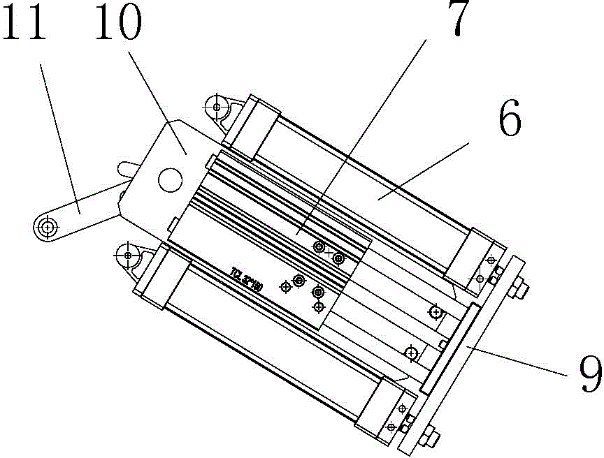
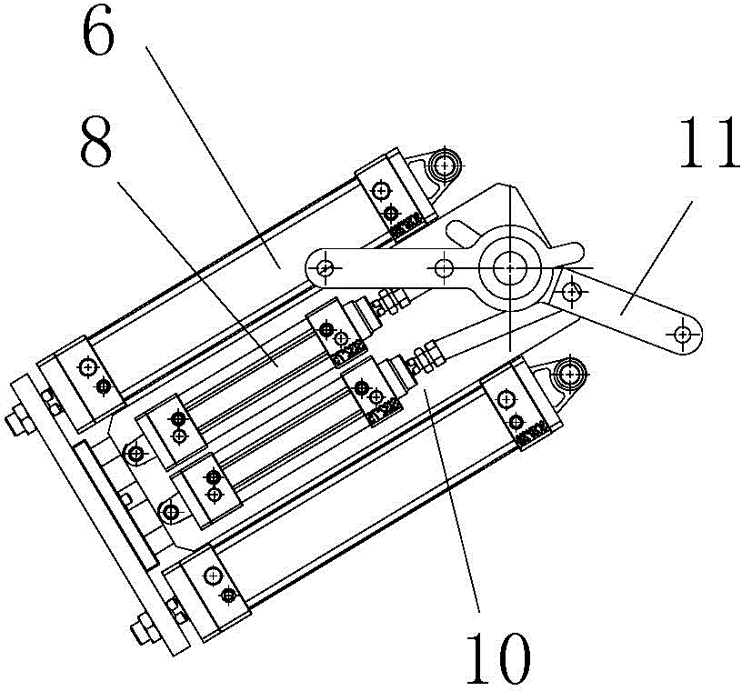
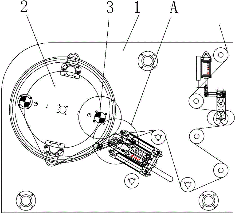
[0021] Such as image 3 As shown, it is a structural schematic view of the winder adopting the linear cutter mechanism of this embodiment. This winding machine comprises two brackets 1 positioned at two ends and the roller frame 2 on the mounting bracket 1 that rotates, and two roller frames 2 are provided with two winding rollers 3 that rotate with it, and the two winding rollers 3 There are guide rollers 4 therebetween. The winding machine also includes a linear cutter mechanism. The linear cutter mechanism of this embodiment includes a kissing roller 4 for bonding with the winding roller 3 and a cutter 5 for cutting off the strip. The two ends of the kissing roller 4 are Line...


PUM


Abstract

The invention discloses a linear cutter mechanism for a winding machine. The linear cutter mechanism comprises a kiss roller for being attached to winding rollers and cutters for cutting belt materials. The two ends of the kiss roller are provided with linear driving mechanisms for driving the kiss roller to move along a straight line correspondingly. Each linear driving mechanism comprises a first air cylinder and a second air cylinder, and the axis of a piston rod of the first air cylinder and the axis of a piston rod of the second air cylinder are parallel to each other. The piston rods of the first air cylinders are provided with a connecting plate. The piston rods of the second air cylinders are connected with the connecting plate. Cylinder bodies of the second air cylinders are provide with an installation plate. Third air cylinders with cylinder bodies being in hinged connection with the installation plate are arranged on the installation plate. The kiss roller is rotationally installed on the installation plate in a matched mode. The two ends of each cutter are provided with connecting rods correspondingly. The connecting rods are rotationally installed on the kiss roller in a matched and sleeving mode. Piston rods of the third air cylinders are in hinged connection with the connecting rods. According to the linear cutter mechanism for the winding machine, not only can the using requirement be met, but also the impact force during cutting is small, and the effect that the belt materials can be attached to the winding rollers can be ensured.

Description

technical field [0001] The invention belongs to the technical field of strip coiling mechanisms, and in particular relates to a linear cutter mechanism for a winder. Background technique [0002] The winding and unwinding mechanism is the unwinding or rewinding part of the coil material processing production line. It is mainly used to mechanically unwind the coiled raw materials during unwinding, and is mainly used to mechanically wind the raw materials into coils during winding. The winding and unwinding mechanism is widely used in paper rolls, cloth rolls, plastic rolls and metal coil processing production lines, and the design is diversified according to actual process requirements. [0003] The roll frame of the existing winder is provided with two winding rollers. When one of the winding rollers is finished winding, the roller frame is driven to rotate so that the winding roller rotates to the unloading station, while the other The first winding roller then rotates to ...

Claims


Application Information

Patent Timeline
Patent Type & Authority Applications(China)
IPC IPC(8): B65H19/26B65H19/30B65H19/28B65H18/08B65H79/00B65H23/038B26D1/12B26D7/26B26D5/12
Inventor 李永才
Owner CHONGQING SINSTAR PACKAGING MACHINERY
Why Eureka
Try Eureka