Compound machine

A compound machine and compound device technology, applied in the field of compound machines, can solve the problems of reduced service life and reliability of the winding mechanism, formation of stress concentration, large acting force, etc., to prevent displacement jumping, high reliability, and service life. long effect

Active Publication Date: 2016-07-20
CHONGQING SINSTAR PACKAGING MACHINERY
View PDF24 Cites 1 Cited by
  • Summary
  • Abstract
  • Description
  • Claims
  • Application Information

AI Technical Summary

Problems solved by technology

Although such a winding mechanism can meet the requirements of use to a certain extent, since the roll frame is directly installed on the bracket through the rotating shaft, when the weight of the strip wound on the winding and unwinding roller is large, there will be a gap between the roll frame and the bracket. The rotating fulcrum is subjected to a large force, forming stress concentration and easy damage, resulting in a reduction in the service life and reliability of the winding mechanism

Method used


Image

  • Compound machine
  • Compound machine
  • Compound machine

Examples


Embodiment Construction

[0044] The present invention will be further described below in conjunction with the accompanying drawings and specific embodiments, so that those skilled in the art can better understand the present invention and implement it, but the examples given are not intended to limit the present invention.

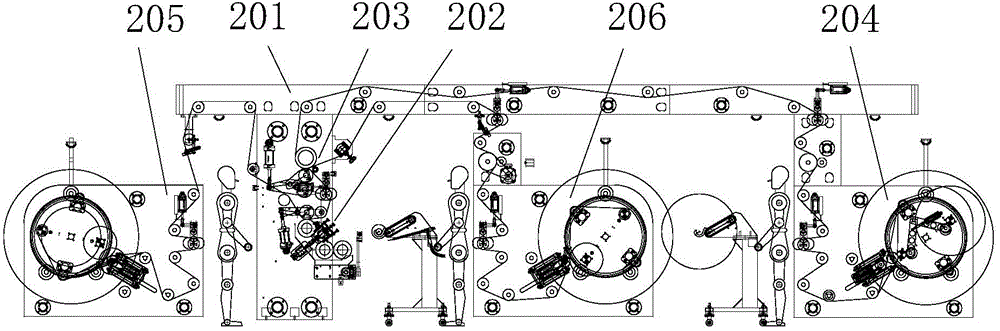
[0045] Such as figure 1 Shown is a schematic structural diagram of a compound machine embodiment of the present invention. The composite machine of this embodiment includes a top guide roller assembly 201, a coating device 202, a composite device 203, a winding mechanism 204, a first unwinding mechanism 205 corresponding to the coating device 202, and a first unwinding mechanism 205 corresponding to the composite device 203. The second unwinding mechanism 206, the winding mechanism 204, the first unwinding mechanism 205 and the second unwinding mechanism 206 all adopt the disc type winding and unwinding mechanism with the same structure. The coating device 202 and the composite d...


PUM


Abstract

The invention discloses a compound machine. The compound machine comprises a roof guide roller assembly, a coating device, a compound device, a winding mechanism, a first unwinding mechanism arranged in a manner of corresponding to the coating device and a second unwinding mechanism arranged in a manner of corresponding to the compound device; the winding mechanism, the first unwinding mechanism and the second unwinding mechanism are disc type winding and unwinding mechanisms; each disc type winding and unwinding mechanism comprises two supports located at the two ends, coaxial installation holes are correspondingly formed in the two supports, disc type roller supports are arranged in the installation holes, two winding and unwinding rollers are arranged between the two corresponding disc type roller supports, and rotating support units are arranged on the supports; compression roller mechanisms are further arranged on the disc type roller supports of the winding mechanism, each compression roller mechanism comprises a compression roller, and compression roller arms are arranged at the two ends of each compression roller and are rotationally installed on the corresponding disc type roller supports in a matched manner; and each disc type roller support is provided with a compression roller air cylinder used for driving the corresponding compression rollers to rotate, a cylinder body of each compression roller air cylinder is rotationally installed on the corresponding disc type roller support in a matched manner, and a piston rod of each compression roller air cylinder is hinged to the corresponding compression roller arm.

Description

technical field [0001] The invention belongs to the technical field of packaging and printing equipment, in particular to a composite machine. Background technique [0002] The composite machine is mainly used for the mechanical equipment that combines two or more layers of the same or different materials with a special adhesive. The existing composite machine generally includes a coating device, at least two unwinding devices and a winding device. The strips wound on the unwinding device are guided by guide rollers and then transported to the coating device for integration, and then guided to the winding device. Winding at the winding device. [0003] The structure of the winding device is similar to that of the unwinding device. It generally includes brackets at both ends, with a roller frame between the two brackets, and two winding and unwinding rollers between the two roller frames, and the two roller frames rotate separately Fits on two brackets. The winding and unw...

Claims


Application Information

Patent Timeline
Patent Type & Authority Applications(China)
IPC IPC(8): B65H37/04B65H16/06B65H18/02B65H18/26B65H19/26B65H79/00
CPCY02E60/10
Inventor 李永才
Owner CHONGQING SINSTAR PACKAGING MACHINERY
Why Eureka
Try Eureka